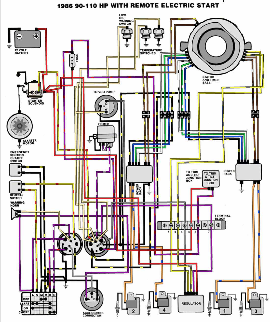
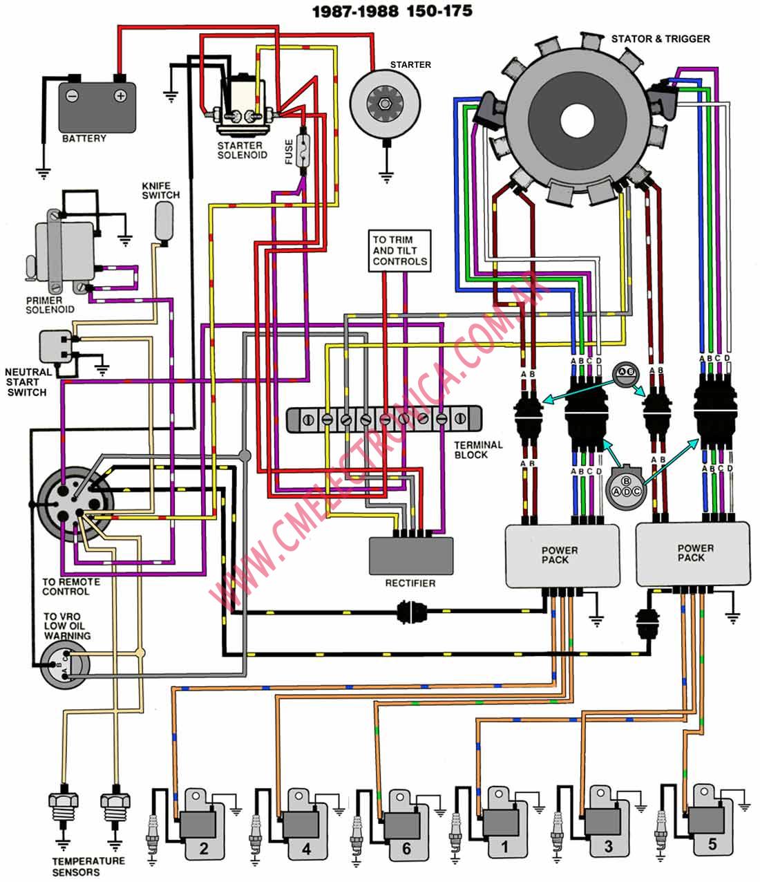
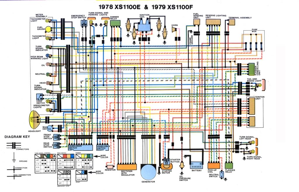
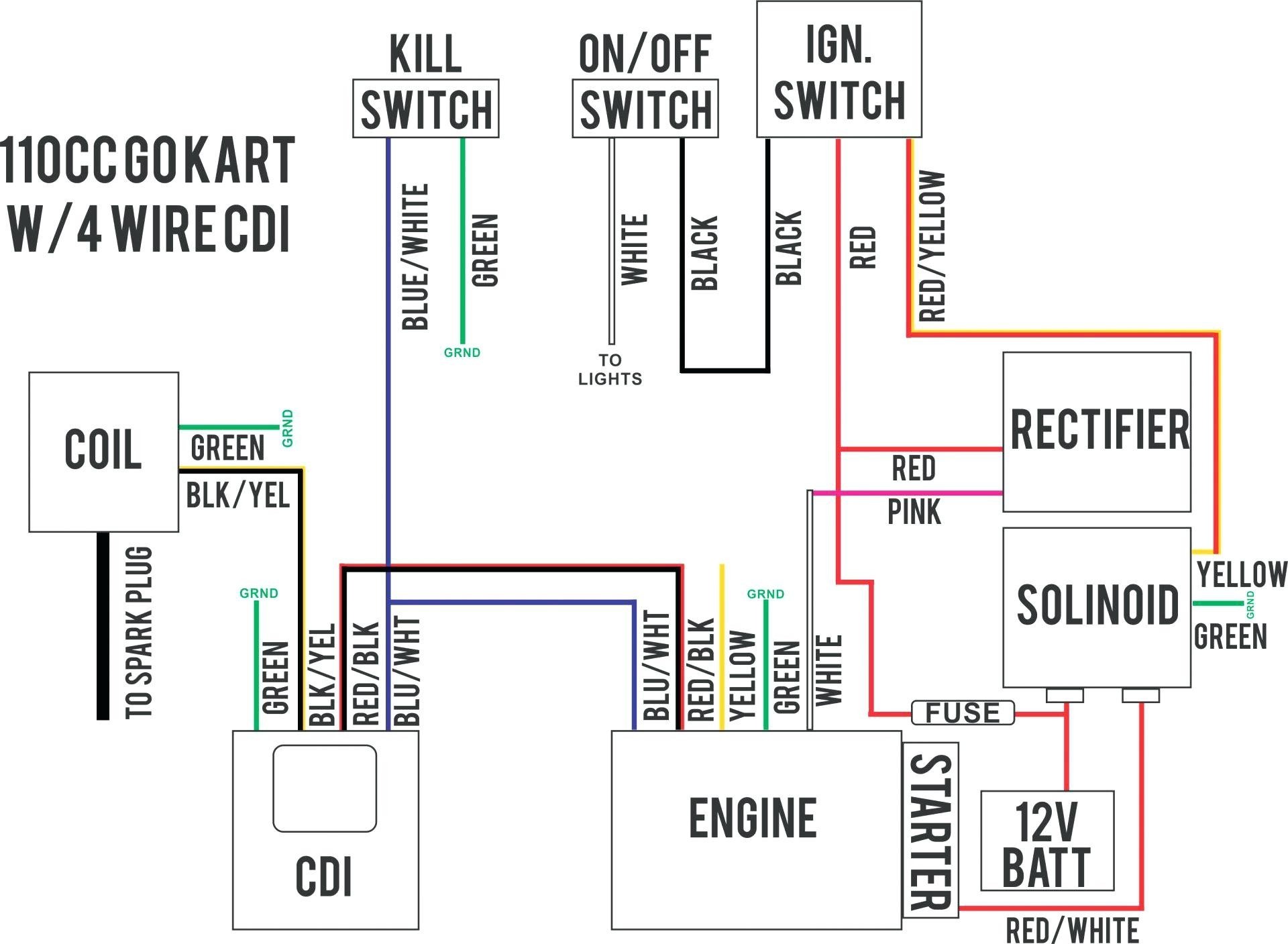
A wiring diagram is a streamlined traditional pictorial depiction of an electrical circuit. It shows the parts of the circuit as streamlined forms and also the power and signal connections in between the tools.
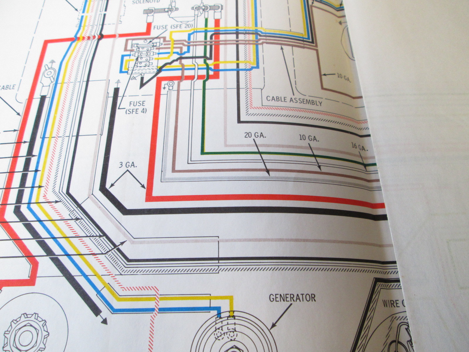
1965 Yamaha Wiring Diagram Chevrolet 10 Brillenstudio
Yamaha outboard ignition switch diagram. Here is a listing of common color codes for yamaha outboard motors. Variety of yamaha outboard ignition switch wiring diagram. Each part should be set and linked to other parts in particular way. The primary voltage is not battery dependent it is generated in the engine. A wiring diagram is a simplified standard photographic depiction of an electrical circuit. Manufactured by cdi electronics.
The kill circuit takes primary voltage from the engine to the ignition switch. There is an industry standard set of wire codes in general use by most manufacturers except yamaha. Yamaha outboard ignition switch wiring diagram yamaha 115 outboard ignition switch wiring diagram yamaha outboard ignition switch wiring diagram yamaha outboard key switch wiring diagram every electrical structure consists of various unique components. It reveals the elements of the circuit as simplified shapes as well as the power and also signal links in between the tools. Ignition switch wiring diagrams this is way my 75 115 johnnie works and the diagrams above are consistant with mine. Colors on wires match factory color codes.
The igniton switch grounds the primary voltage to kill the engine. Colors listed here may vary with year model but in general should be a good guide when tracing yamaha wiring troubles. Variety of yamaha key switch wiring diagram. Ignition switch for yamaha dash mount ignition switch for 2 stroke outboard motors dual engine application. If not the structure wont function as it ought to be.
