Photocell wiring diagram with contactor 7. How to install a single tube light with electromagnetic ballast.

Parmida 20 Pack 4ft Led T8 Ballast Bypass Type B Light Tube 18w Ul Listed For Single Ended Amp Dual Ended Connection 5000k 2200lm Frosted Lens T8
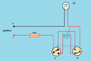
Tube light wiring diagram pdf. It shows the components of the circuit as simplified forms and also the power and signal links between the tools. Assortment of t8 led tube light wiring diagram. Photocell wiring diagram 6. Remove the ballast from the. Tube lights are most used light source and here tube light connection circuit and wiring diagram given with explanation. Connection of tube light is very simple because it has few wiring points only.
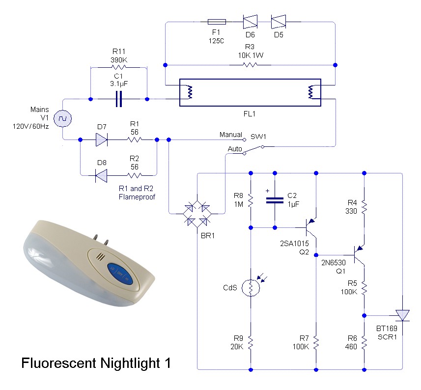
A glow starter or commonly known as starter is used in the tube light circuit to provide an initial current to filaments of the tube light. Wiring diagram of single tube light installation with electromagnetic ballast. When an ac voltage is applied to a tube light fixture the voltage passes through the choke the starter and the filaments of the tube. Its purpose is to show you step by step how to convert your current 4 foot t8 or t12 fluorescent tube light fixture to use the starled ballast. Different electrical symbols are used to make the wiring diagram below. This article gives a details about double tube light connection by using single ballast or choke some electronic choke not support this connection check the ballast specification and watts level before make this type of connection.
How do lightbulbs work. The starter is made up of a discharbe bulb with two electrodes next to it. Wiring diagram how to bypass ballast for led tube. The wiring process of fluorescent tube lamplight with ballast starter is quite easy and simple. From the junction box the neutral wire is not taken out to the switch board rather it is taken out from the junction box and. Wiring diagram here two tube lights are used in our case each one is 20 watts each tube light will have.
A wiring diagram is a simplified standard pictorial representation of an electrical circuit. Day night sensor switch circuit 8. It shows the parts of the circuit as streamlined forms and also the power and signal connections between the gadgets. Street light sensor connection 10. A wiring diagram is a simplified conventional photographic depiction of an electric circuit. Assortment of led tube light wiring diagram.
The filaments light up and instantly warm up the tube. Cut back additional wiring on opposite side of ballast as the led tube lamp only requires power at one end. This post fluorescent light wiring diagram tube light circuit is about how to wiring fluorescent light and how a fluorescent tube light works. Light sensor switch 9. Automatic day night light. The tube light or fluorescent light is a low pressure mercury vapor gas discharge lamp and it uses fluorescent to produce white light.
This principle of the choke is exploited in lighting a fluorescent tube light. In most cases when we buy a fluorescent light it comes in a complete set with all wire connected.


