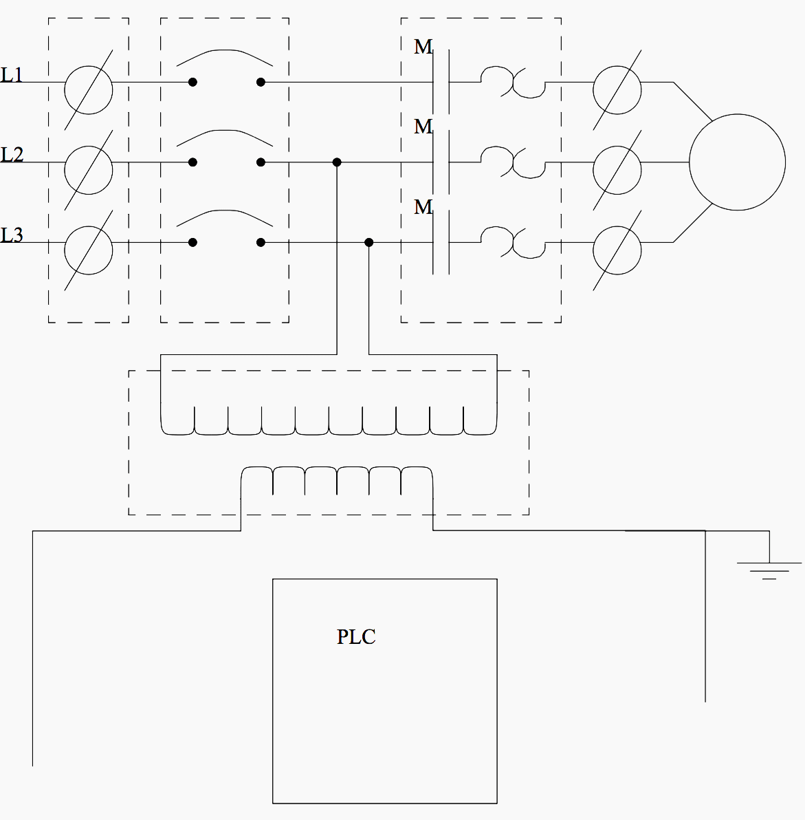
This figure shows the e stop wired to cutoff power to all of the devices in the circuit including the plc. Wiring the s7 400 4 networking 5 commissioning 6 maintenance 7 appendices assembling and installing systems a guidelines for handling electro statically sensitive devices esd b.

Ladder Diagrams And The Plc For Electrical Engineers
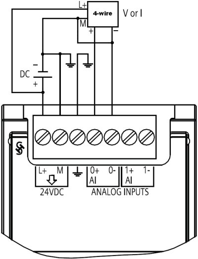
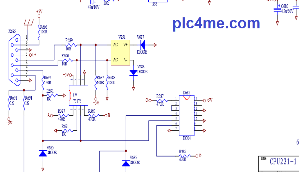
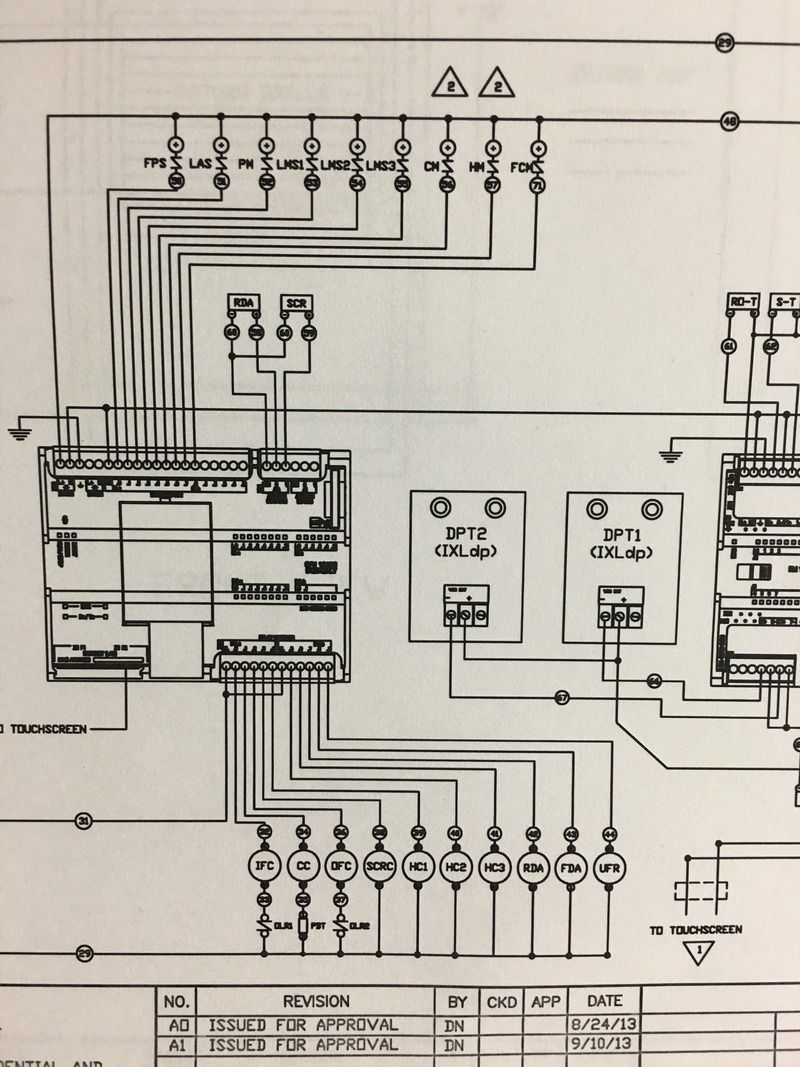
Siemens plc wiring diagram. Pry off the connector cover using a suitable tool. Introduction to plc ladder diagrams. When including a plc in the ladder diagram still remains. This video describes how to wire your controller. In this video the connection to the wiring of siemens plc s7 200 has been done with an easy way. But it does tend to become more complex.
You will find information on which voltage the plug is approved for on the side of the plug. Connect the mains cable in the plug according to the connection diagram. Siemens offers a number of training courses to familiarize you with the simatic s7 automation system. Please contact your regional training center or our central. Figure 5 below shows a schematic diagram for a plc based motor control system similar to the previous motor control example. Wiring getting started 032013 a5e03973906 01 9 wiring the mains connection plug 3 procedure 1.
As an introduction to ladder diagrams consider the simple wiring diagram for an electrical circuit in figure 1athe diagram shows the circuit for switching on or off an electric motor. Hi friendsi bought a sinamics v60 drive and 1fl5 servo motor with itnow i need to run this servo motor through my s7 200 cpu224 cn plcthe connections inthe manual is not clearcan any one help me by specifing the wiring diagram of plc outputs with the sinamics v60 drive terminals.


