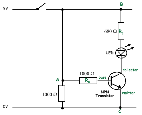
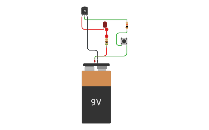
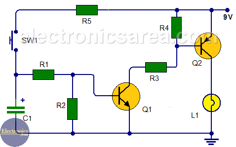
Transistor as a switch. It is just enough to make led b glow dimly.

Using Transistors As Switches
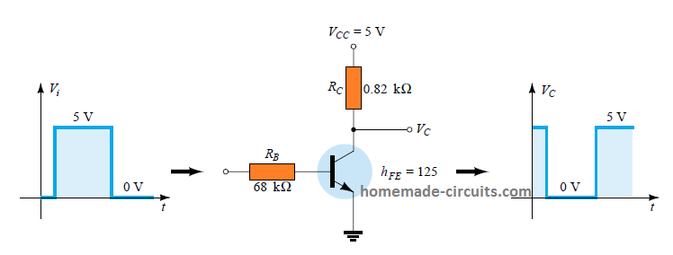
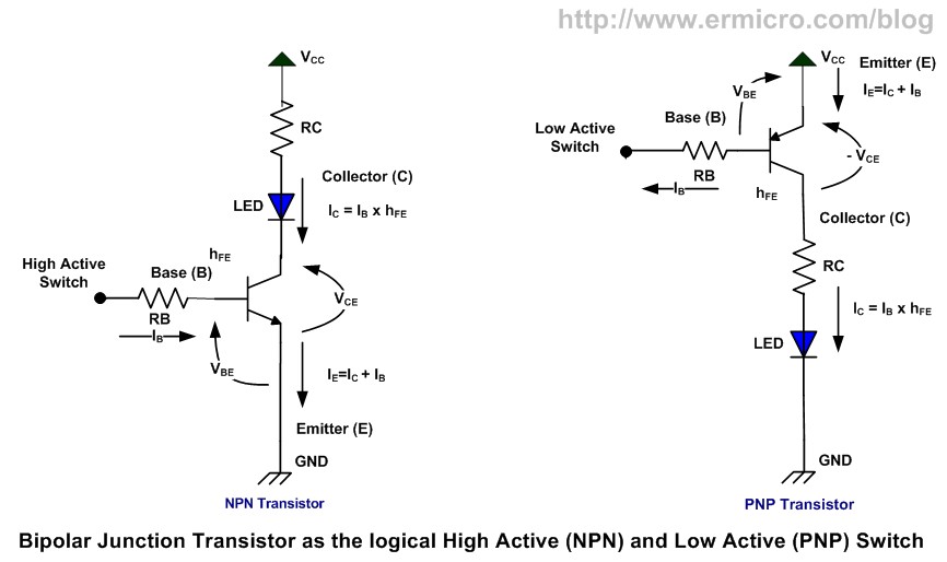
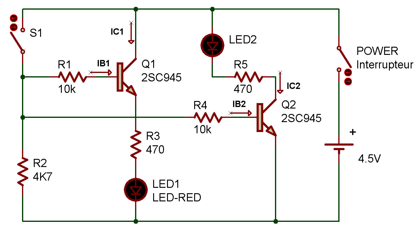
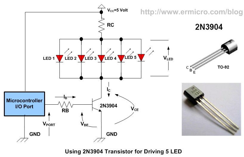
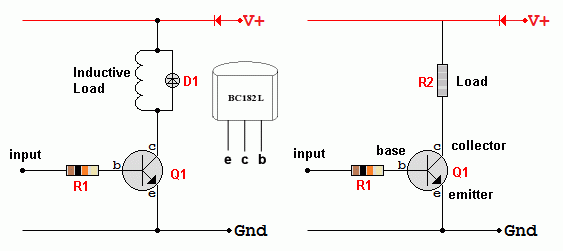
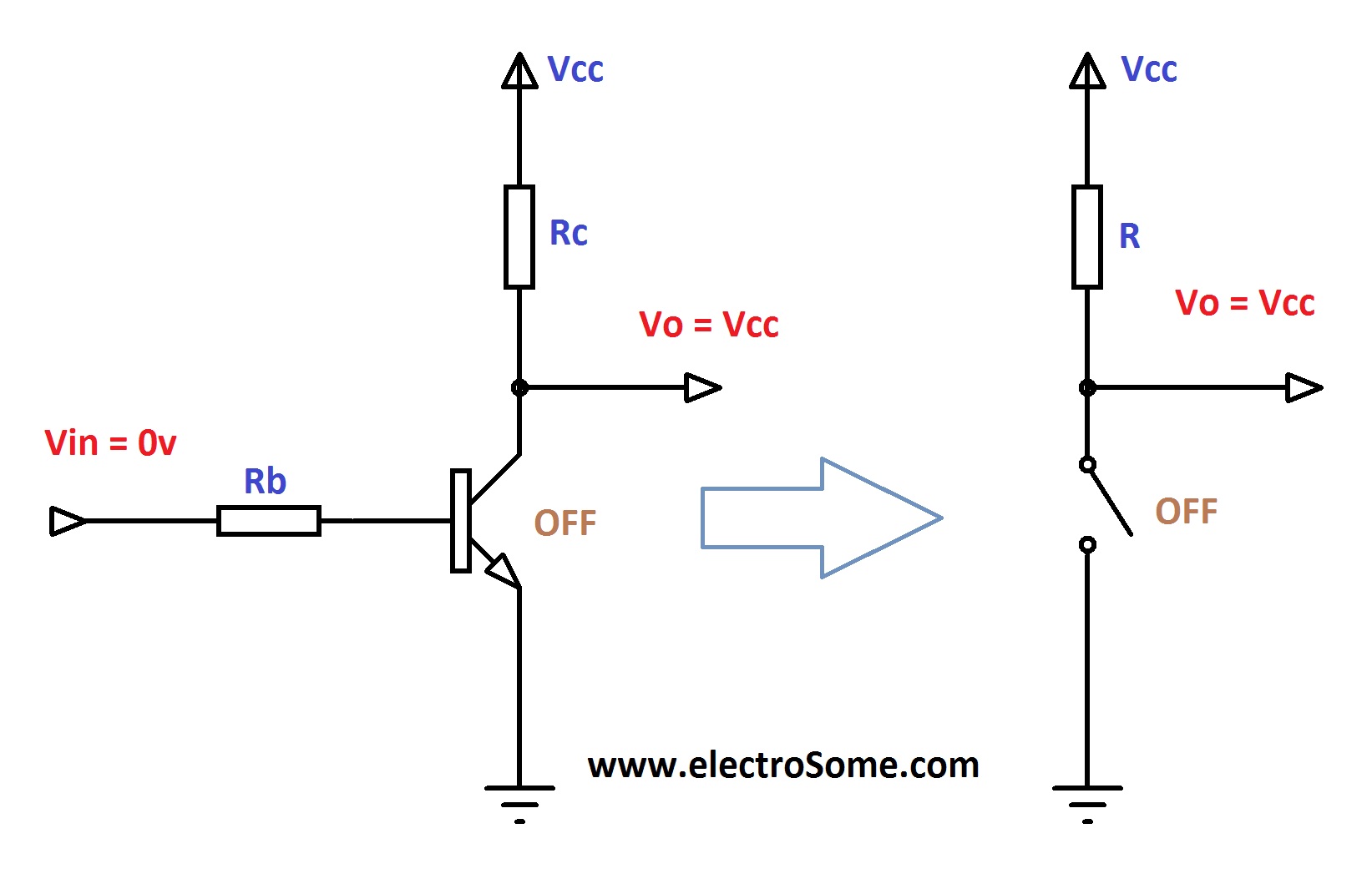
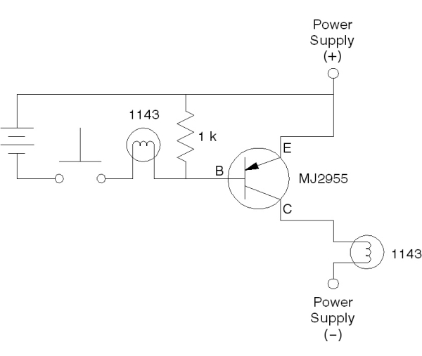
Transistor as a switch circuit diagram. If using a pnp transistor negative voltage is supplied to the collector. Circuit diagram transistor as a switch transistor as a switch circuit diagram. In most cases output is taken from collector but in some cases. This is a schematic diagram for a circuit that uses an npn transistor as a switch that turns an led on or off. The diagram shows the two current paths through a transistor. The areas of operation for a transistor switch are known as the saturation region and the cut off region.
Both npn and pnp transistors can be used as switches. The switch is on when the base is saturated so that collector current can flow without restriction. The small base current controls the larger collector current. Look at this circuit component by. The same setup to set the transistor as a switch is also to set it up as an amplifier. In this circuit the transistor acts as a switch and an amplifier.
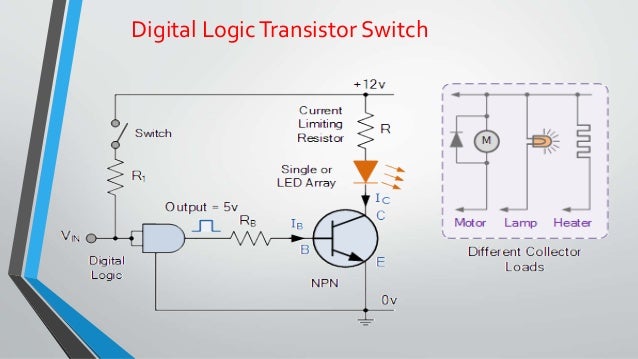
This type solid state switching offers significant reliability and lower cost as compared with conventional relays. The transistor amplifies this small current to allow a larger current to flow through from its collector c to its emitter e. This electrical current switches the transistor on so the transistor can now power its load which is the motor. A transistor is used for switching operation for opening or closing of a circuit. The transistor is off when theres no bias voltage or when the bias voltage is less than 07 v. If the circuit uses the bipolar transistor as a switch then the biasing of the transistor either npn or pnp is arranged to operate the transistor at both sides of the i v characteristics curves we have seen previously.
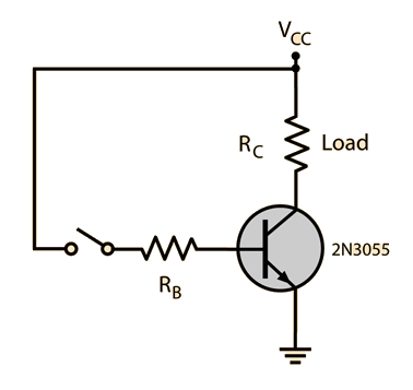
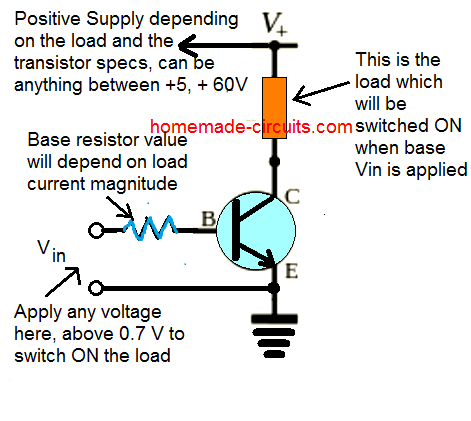
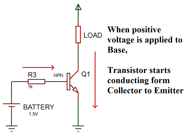
When the switch is closed a small current flows into the base b of the transistor. From the above circuit we can see that the control input vin is given to base through a current limiting resistor rb and rc is the collector resistor which limits the current through the transistor.

