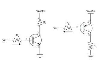
This type of switching is used for negative ground configurations. Pnp transistor is a type of bipolar junction transistor.

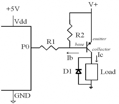
Using Micro Controller To Switch Pnp Transistor Avr Freaks
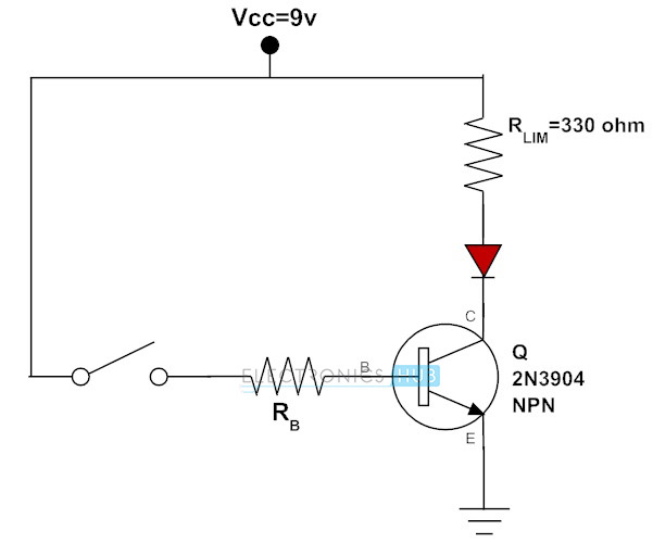
Pnp transistor as a switch circuit diagram. Pnp transistor as a switch. The transistor was invented by william shockley in 1947a transistor is a three terminal semiconductor device which can be used for switching applications amplification of weak signals and in quantities of thousands and millions of transistors are interconnected and embedded into a tiny integrated circuitchip which makes computer memories. Simply the collector and emitter are. This circuit will switch to load when the output from ic is high v. Pnp transistor as a switch the circuit in the above figure shows the pnp transistor as a switch. The circuit diagram shows the connection of the npn transistor.
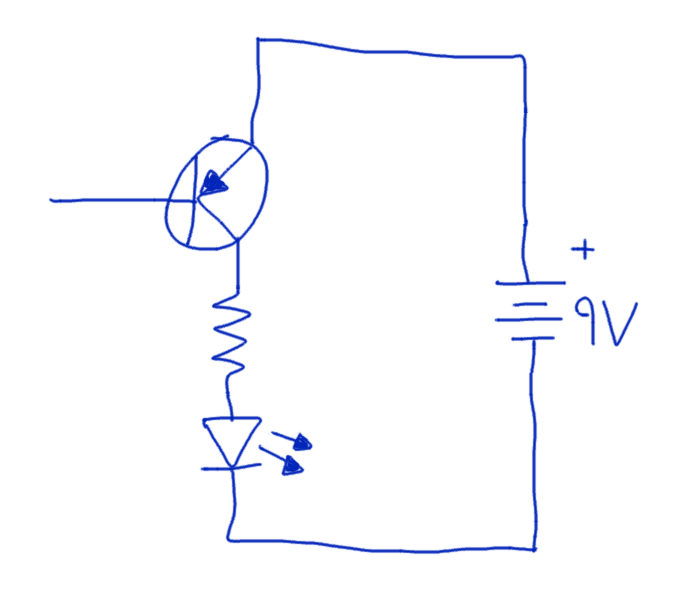
Negative voltage then the pnp transistor is in on now the supply voltage at emitter conducts and the output pin pulled up to the. Pnp transistors can also be used as switching devices and an example of a pnp transistor switch is shown below. So 3v is connected to the emitter of the transistor. When there is no voltage on base terminal it works as a close switch between collector and emitter. A pnp transistor circuit. On the other hand if you want to continue loading when the output from ic is low 0v look at the circuit for the pnp transistor below.
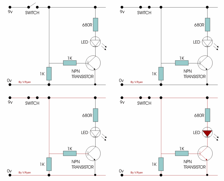
And a normally open pushbutton is connected to the base of the transistor. The areas of operation for a transistor switch are known as the saturation region and the cut off region. Pnp transistor switching circuit the concept of pnp transistor as a switch is that the current stops flow from collector to emitter only when a minimum voltage of 07v is supplied to the base terminal. A transistor switch which is used for. While discussing its structure in comparison with n p n it is completely different. The operation of this circuit is very simple if the input pin of transistor base is connected to ground ie.
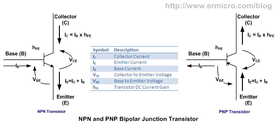
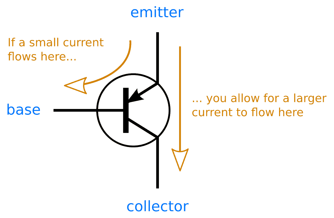
This dc signal is further amplified by the npn transistor 2n4401 and sends it to the base of the pnp darlington transistor bc516. For the pnp transistor the base terminal is always negatively biased with respect to the emitter. Generally the pnp transistor can replace npn transistors in most electronic circuits the only difference is the polarities of the voltages and the directions of the current flow. Pnp transistor works same as npn for a switching operation but the current flows from the base. Working of the circuit is straightforward when the two 1n34 germanium diodes get an rf signal then they convert it into dc signal. This transistor also consists of three terminals known as collector emitter and base.
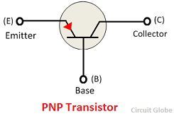
Thus doing it switch on and enact the bell. If the circuit uses the bipolar transistor as a switch then the biasing of the transistor either npn or pnp is arranged to operate the transistor at both sides of the i v characteristics curves we have seen previously. Below is the circuit for connecting a pnp transistor which can function as a switch or an amplifier.
