Do not see that in the electrical diagram. One way to classify switches is by the connections they make.

Safety Circuit Examples Of Safety Components Technical
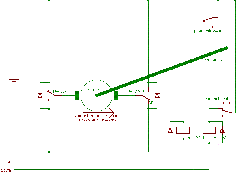
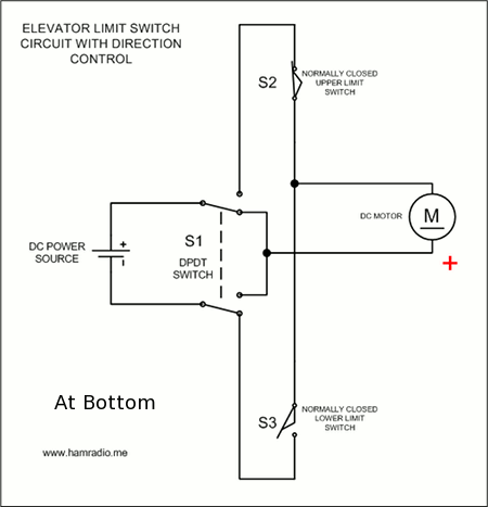
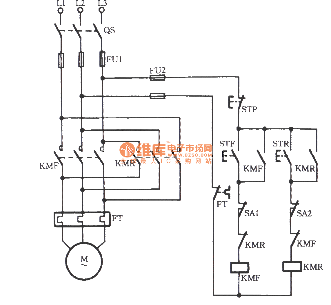
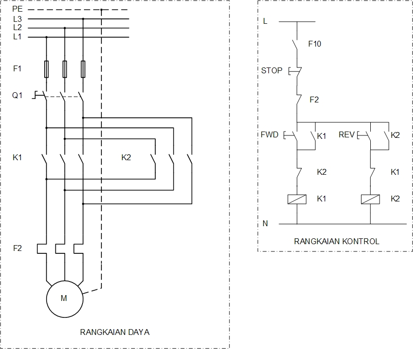
Limit switch circuit diagram. In addition to the onoff switch many circuits contain switches that control how the circuit works or activate different features of the circuit. Most electronic circuits contain an onoff switch. Circuit nodes are shown in the rendered circuit above. The relay is what latches the motor on when the weight reaches a low closing a no normally open limit switch. A limit switch is used to control electrical devices by breaking and completing electrical circuits. This circuit was created by a member of the community and has no affiliation to the circuit diagram project.
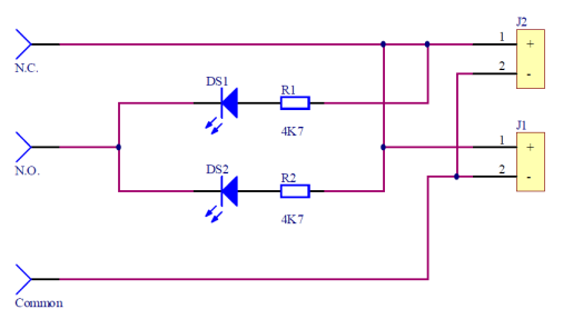
The engine kill circuit consists of the key switch a kill limit switch that is activated. The main function of the limit switch is to open or close an electric circuit when the physical limit of the operation of the controlled device has reached. Most of the limit switches in this design share a common terminal between the nc and no contacts like this. In the common latching circuit i used the motor would be powered switched using a relay. Engine kill circuit reverse buzzer circuit. Limit switch working principle the limit switch is like a 1 no 1 nc push button.
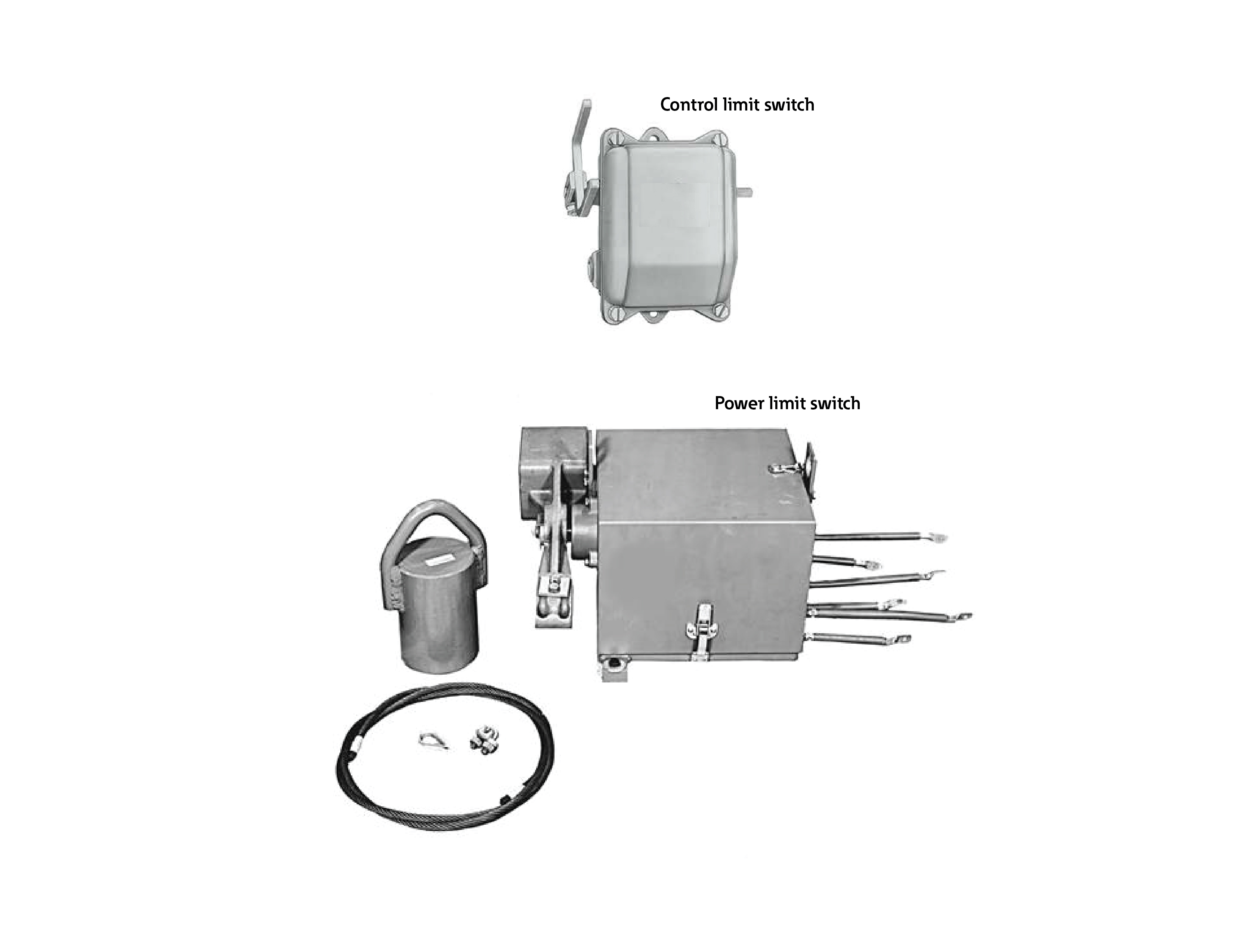
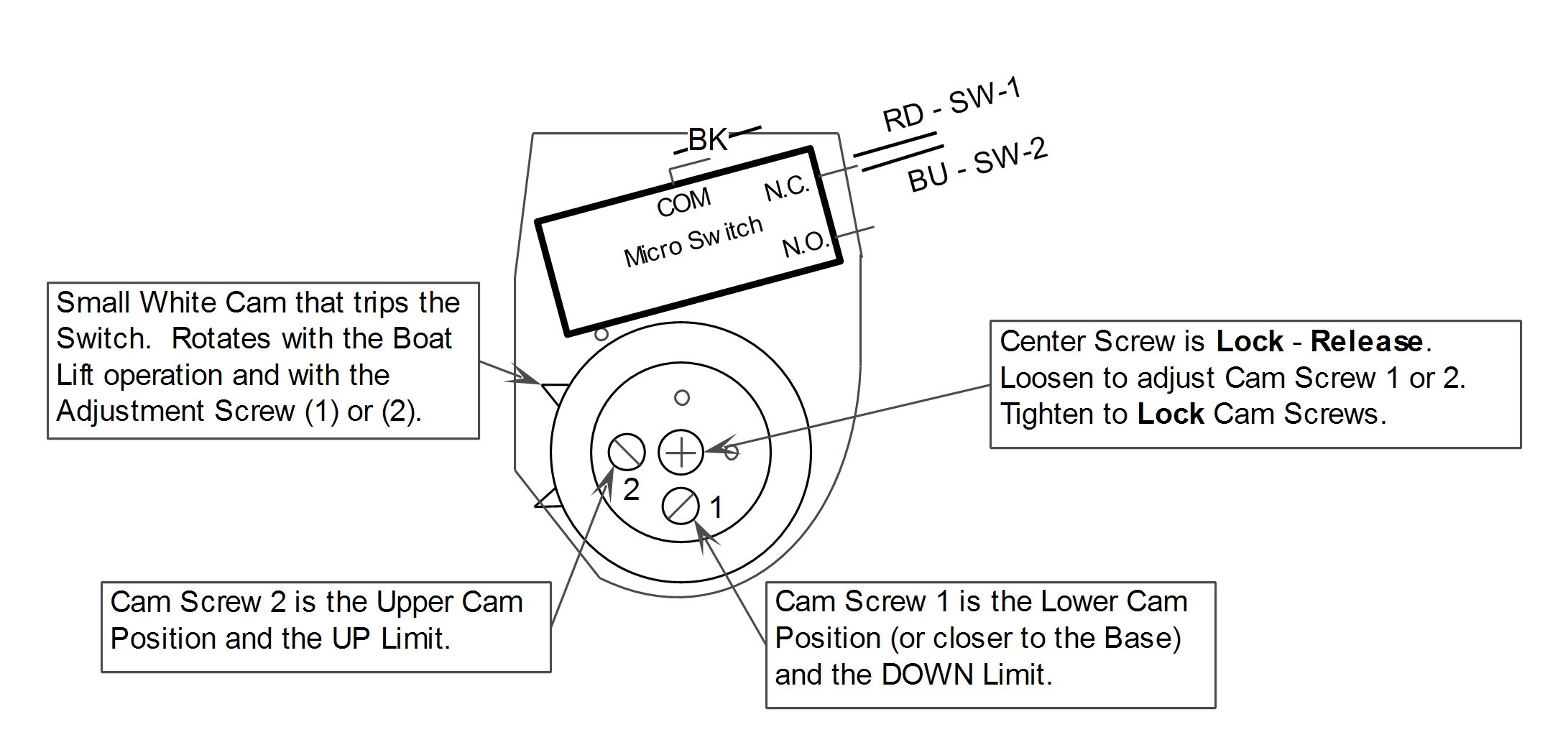
Limit switch styles. The power input terminal is called the common terminal and is used to connect the switch to a power source. We have accumulated several images ideally this image is useful for you and assist you in finding the solution you are searching for. If you were under the impression that switches simply turn circuits on and off. The push button is actuated by hand whereas the limit switch is operated mechanically. The majority of new industrial applications today utilize the plug in design switch due to its superior sealing and ruggedness.
Cddx contact statistics. When i unplug the wires from the top micro switch it does not start so that must be the starter micro switch. Web editor embed. It is abbreviated com the other terminals are the normally open no. Club car fe manual online. In my simple drawing s1 is a nc normally closed limit top and s2 is a no limit switch.
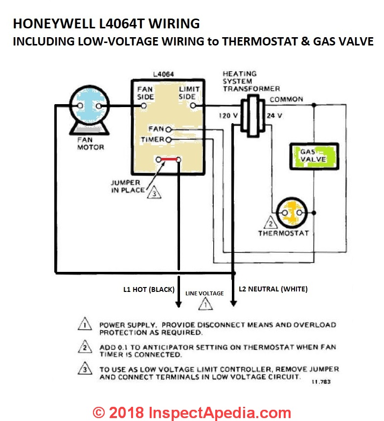
A typical limit switch design uses a lever with a roller tip to make contact with the moving part. It has three terminals. The switch body can be quickly and easily replaced in the field without having to rewire the connections to the terminals in the receptacle. Limit switch circuit by anna cusack. Honeywell fan limit switch wiring diagram thanks for visiting my website this blog post will discuss concerning honeywell fan limit switch wiring diagram. The screw terminals on the switch body provide connection points with the nc and no contacts inside the switch.

