Owing to its characteristics to behave at any electrical power factor it is used in power system in situations where static capacitors are expensive. These motors have a position sensor integrated within the motor which provides a low level signal with a frequency proportional to the speed of rotation of the motor.

The Synchronous Motor
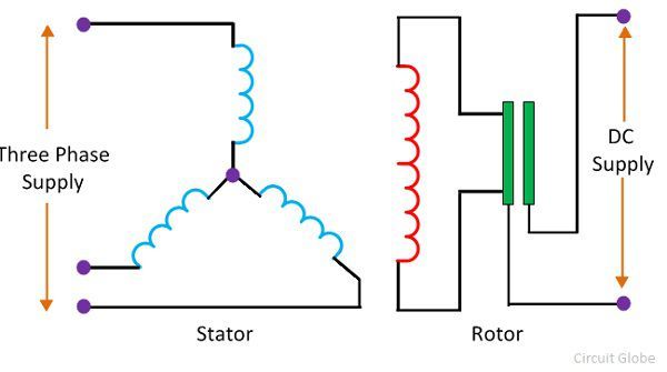
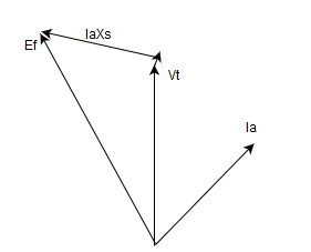
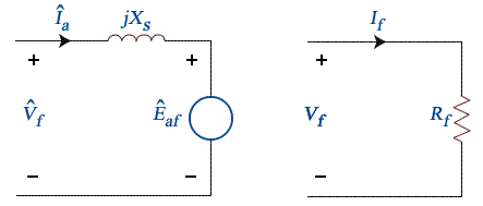
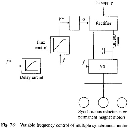
Synchronous motor diagram. We will discuss here the simplest way of drawing the phasor diagram for synchronous motor and we will also discuss advantages of drawing the phasor diagram. The motor which runs at synchronous speed is known as the synchronous motor. 10 model diagram of synchronous motor. The block diagram shows the drive electronics associated with a low voltage 12 v dc synchronous motor. Construction of a synchronous motor is similar to an alternator ac generatora same synchronous machine can be used as a synchronous motor or as an alternator. Synchronous motor and induction motor are the most widely used types of ac motor.
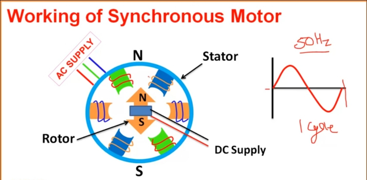
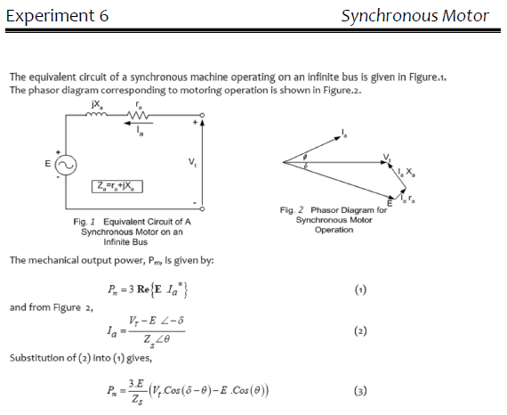
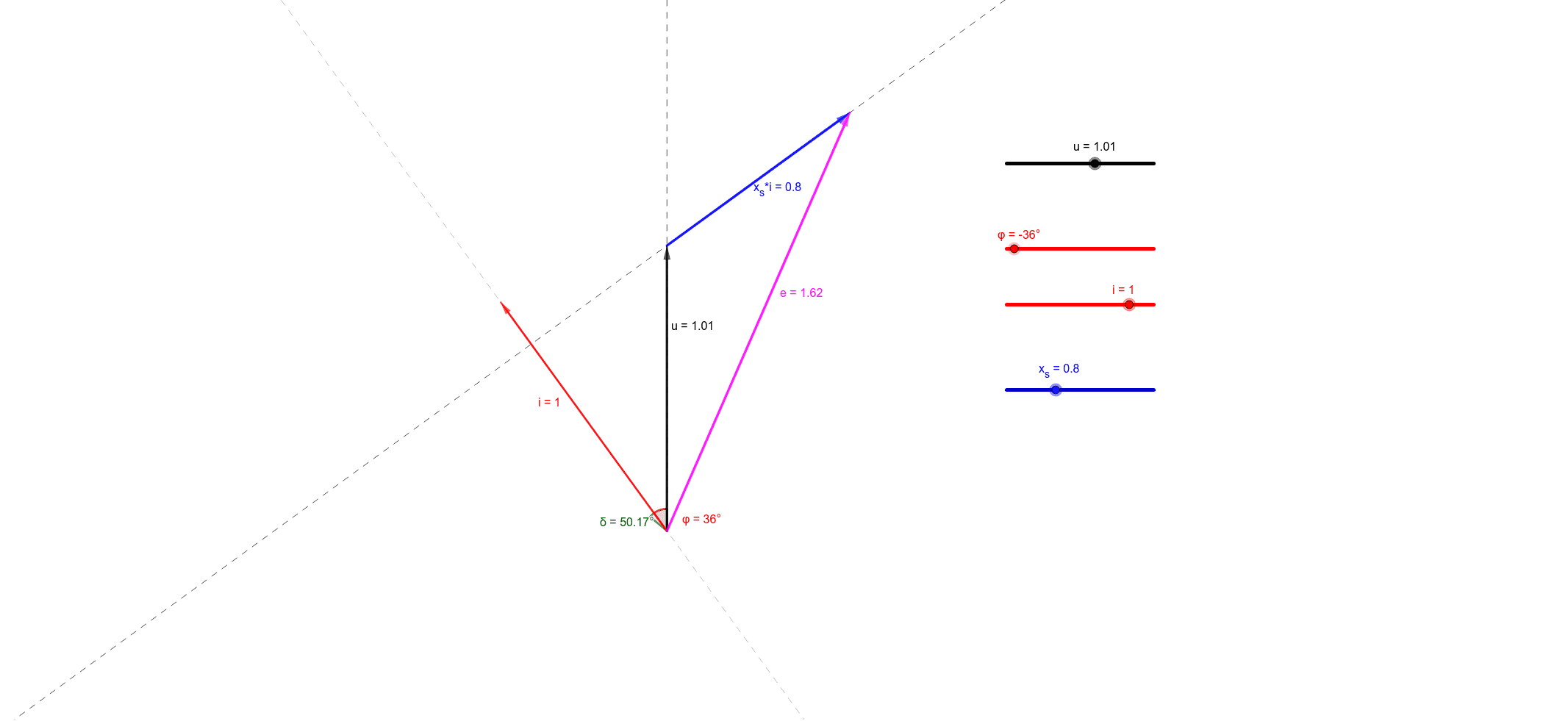
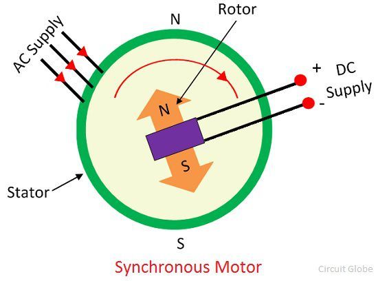
Synchronous motors are available in a wide range generally rated between 150kw to 15mw with speeds ranging from 150 to 1800 rpm. Field structure is stimulated by direct current in synchronous motor. Synchronous motor finds application where operating speed is less around 500 rpm and high power is required. With a known terminal voltage we can construct phasor diagrams for the synchronous motor as shown in figure 2. A synchronous electric motor is an ac motor in which at steady state the rotation of the shaft is synchronized with the frequency of the supply current. The working principle of synchronous motor is explained in this articlewhen a 3 phase supply is given to the stator of a 3 phase wound synchronous motor a rotating field is set up in anticlockwise direction which rotates at a synchronous speed ns 120fp.
Due to the rotating magnetic field the voltage induced in the stator winding and this voltage is called counter emf e. Before we draw phasor diagram let us write the various notations for each quantity at one place. The synchronous motor is used for converting the electrical energy into mechanical energy. Here we will use. Electronic synchronous motor. The rotation period is exactly equal to an integral number of ac cycles.
The synchronous speed is the constant speed at which motor generates the electromotive force. Model diagram and phasor diagram of synchronous motor. 34 mounting the motor 45 341 installation and connection of ip67 kit accessory 47 35 electrical installation 48 351 connectors and connector assignments 48 bmp table of contents synchronous motor 3 13981 v13 012017. Synchronous motor having no load connected to its shaft is used for power factor improvement. Application of synchronous motors. Synchronous motors contain multiphase ac electromagnets on the stator of the motor that create a magnetic field which rotates in time with the oscillations of the line.
Synchronous motor phasor diagram equation 2 is the preferred form since the terminal voltage is normally chosen as the reference phasor for purposes of drawing a phasor diagram.

