The rotation period is exactly equal to an integral number of ac cycles. The block diagram shows the drive electronics associated with a low voltage 12 v dc synchronous motor.

Phasor Diagram For Synchronous Motor Electrical4u
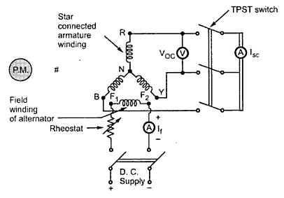
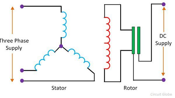
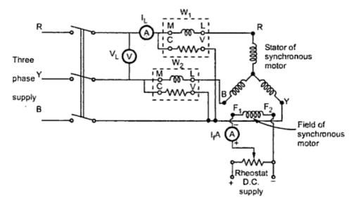
Synchronous motor connection diagram. Chancs motor is a professional motor supplier. Synchronous motor finds application where operating speed is less around 500 rpm and high power is required. Synchronous motors contain multiphase ac electromagnets on the stator of the motor that create a magnetic field which rotates in time with the oscillations of the line. A synchronous motor rotates at a constant speed in proportion to the ac power. Synchronous motor having no load connected to its shaft is used for power factor improvement. Owing to its characteristics to behave at any electrical power factor it is used in power system in situations where static capacitors are expensive.
A synchronous electric motor is an ac motor in which at steady state the rotation of the shaft is synchronized with the frequency of the supply current. All motors shall be designed for across the line starting at full rated voltage. In this lesson well learn to read and interpret motor connection diagrams and determine the electrical relationship of the stator windings using motor connection diagrams. 34 mounting the motor 45 341 installation and connection of ip67 kit accessory 47 35 electrical installation 48 351 connectors and connector assignments 48 bmp table of contents synchronous motor 3 13981 v13 012017. Figure 6 contains a diagram showing the connections for operating a slo syn motor as a three lead reversible motor from a single phase source. We can supply different types of motors like synchronous motor dc gear motor stepper motor brushless motor etc in order to help customer connect.
The stepping motor is transformed into a synchronous motor by replacing the wound wire for the ac power specification. Application of synchronous motors. Electronic synchronous motor. 133 for different excitations. The torque developed in a synchronous motor is directly proportional to the applied voltage unlike in an induction motors where it is proportional to the square of voltage. Power angle diagram of synchronous motor.
These motors have a position sensor integrated within the motor which provides a low level signal with a frequency proportional to the speed of rotation of the motor. Single motors connected to captive transformers shall be capable of overcoming the inertia of the load on starting as well as accelerating the load to rated speed under both rated and 70 percent of the rated voltage conditions or voltage conditions specified on data. Synchronous motor starting capabilities. The power angle characteristics of both types of rotor are shown in fig. Since a slo syn motor is inherently a two phase or a three phase device depending on model a phase shifting network is required to convert the single phase excitation into the. A synchronous electric motor is an ac motor distinguished by a rotor spinning with coils passing magnets at the same rate as the alternating current and resulting magnetic field which drives it.


