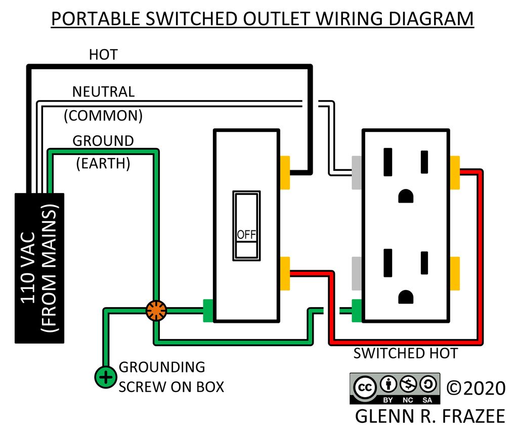
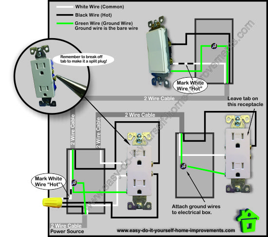
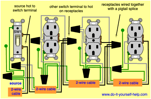
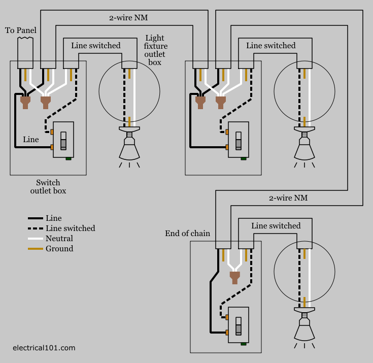
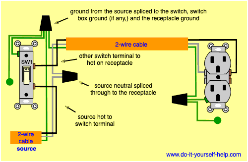
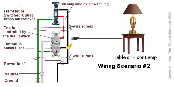
A wiring diagram is a simplified traditional photographic representation of an electric circuit. The diagram below shows the power entering the circuit at the grounded outlet box location then sending power up to the switch and a switched leg back down to the outlet.

Need Help With Gfci Switch Combo Only Two Wir Leviton
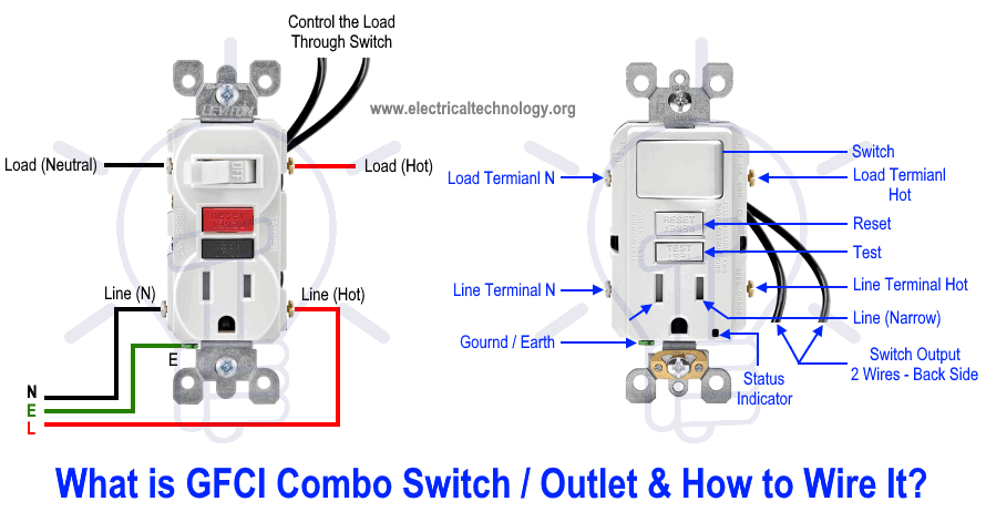
Outlet to switch to outlet diagram. Wiring a gfci combo switchoutlet with protected light outlet receptacle. The hot source at the outlet is spliced to the black wire running to the switch and the hot wires running to the other outlets in. How to wire an outlet from a switch. It means all the connected loads to the load terminals of gfci are protected. You should switch off electrical power from the mains to avoid electrocution. Switch off the mains.
In this special case wiring diagram both light and ordinary outlet is connected to the load terminals of gfci. If a load plugged into the outlet or the disposal causes a short the whole device will trip and neither will work until the danger is removed. The same wiring diagram can be used if the power is instead coming from another outlet and connected to one of the depicted outlets on the end. Ground connection diagram is shown separately. Run the cable from the circuit breaker to the location of the electrical outlet. How to wire an electrical outlet.
A metal tab connects the line right side of the switch and line side of the outlet. Wiring a gfci outlet with combo switch outlet receptacle light switch. Wall outlet switch wiring diagram. Switch controls light and outlet. In the wiring diagram above a hot and a neutral enter the single pole switch box. The light onoff operation can be controlled through the gfci switch while the ordinary outlet is directly connected to the gfci load terminals.
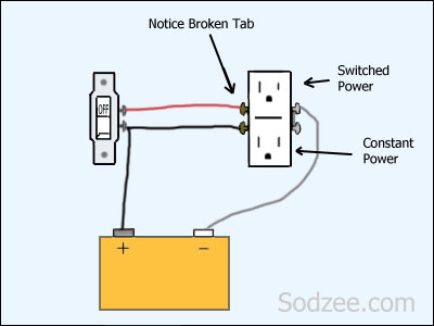
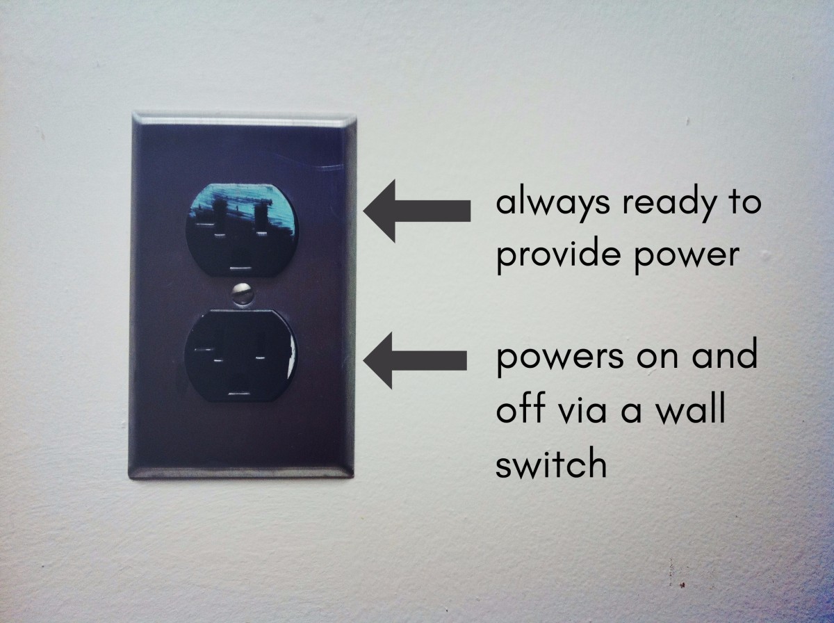
Wiring a switch wiring a light switch diagram 1. It reveals the parts of the circuit as streamlined forms and also the power as well as signal connections between the tools. Assortment of leviton switch outlet combination wiring diagram. Notice that these outlets have the tab removed from the hot side or brass side of the outlet which allows the top half of the plug to be controlled only from the switch. Here a switch has been added to control an existing receptacle. One cant be too careful.
This diagram illustrates the wiring for a cooper gfci combo switch device to control a garbage disposal. Your cable should be long enough to reach each socket. From there a 3 conductor cable is installed to a. Switch controls light only. Switch and the outlet can have different lines in. Here the gfci outlet the switch and disposal are all protected from ground faults.
The switch takes the hot from the middle receptacle here and 3 wire cable runs from there to the new switch location. In this gfci outlet wiring and installation diagram the combo switch outlet spst single way switch and ordinary outlet is connected to the load side of gfci. Electrical outlet wiring wiring electrical outlet for the home home electrical wiring includes 110 volt outlets which are common place in every home. The following diagrams show each wiring configuration. Electrical wire electrical wire for the home. See how wiring electrical outlets for the home are done.
Switched outlet diagram with hot and a neutral entering the switch box.
