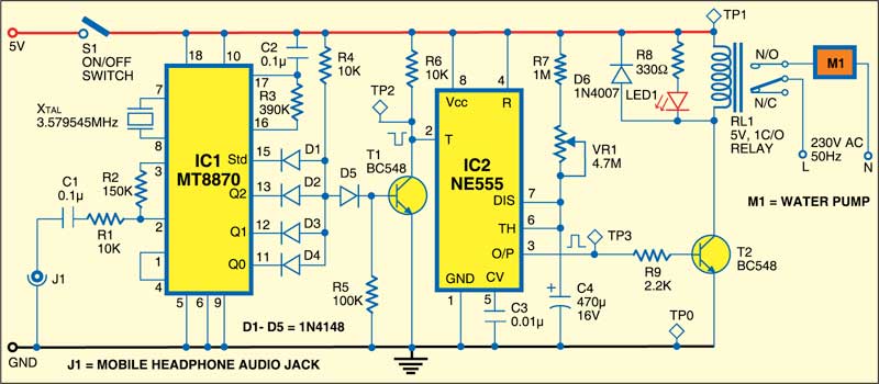
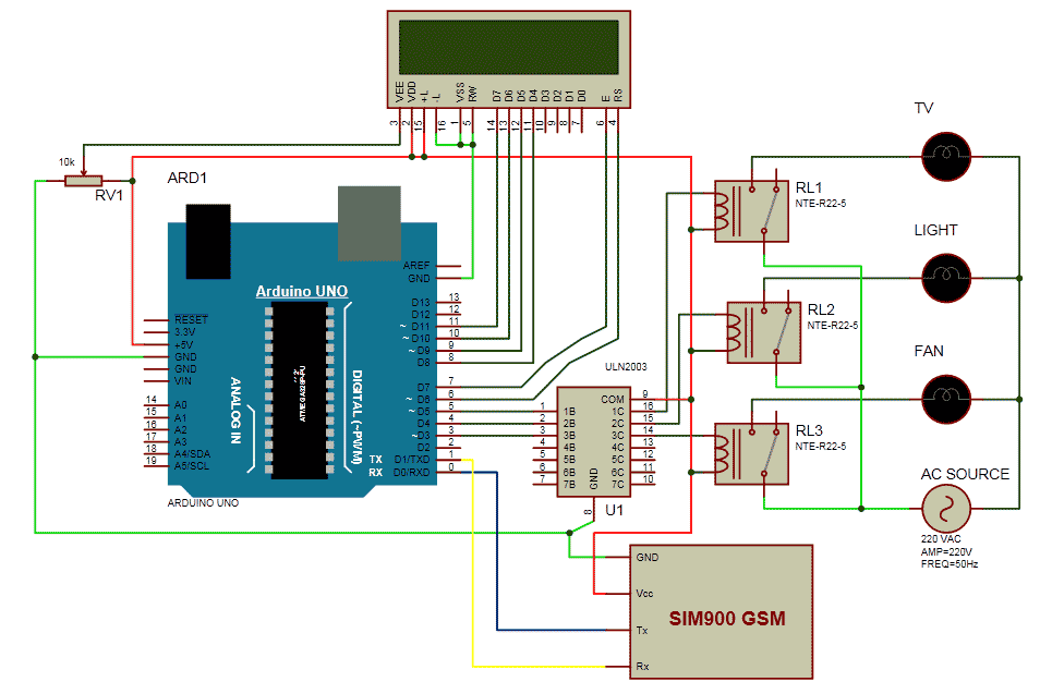
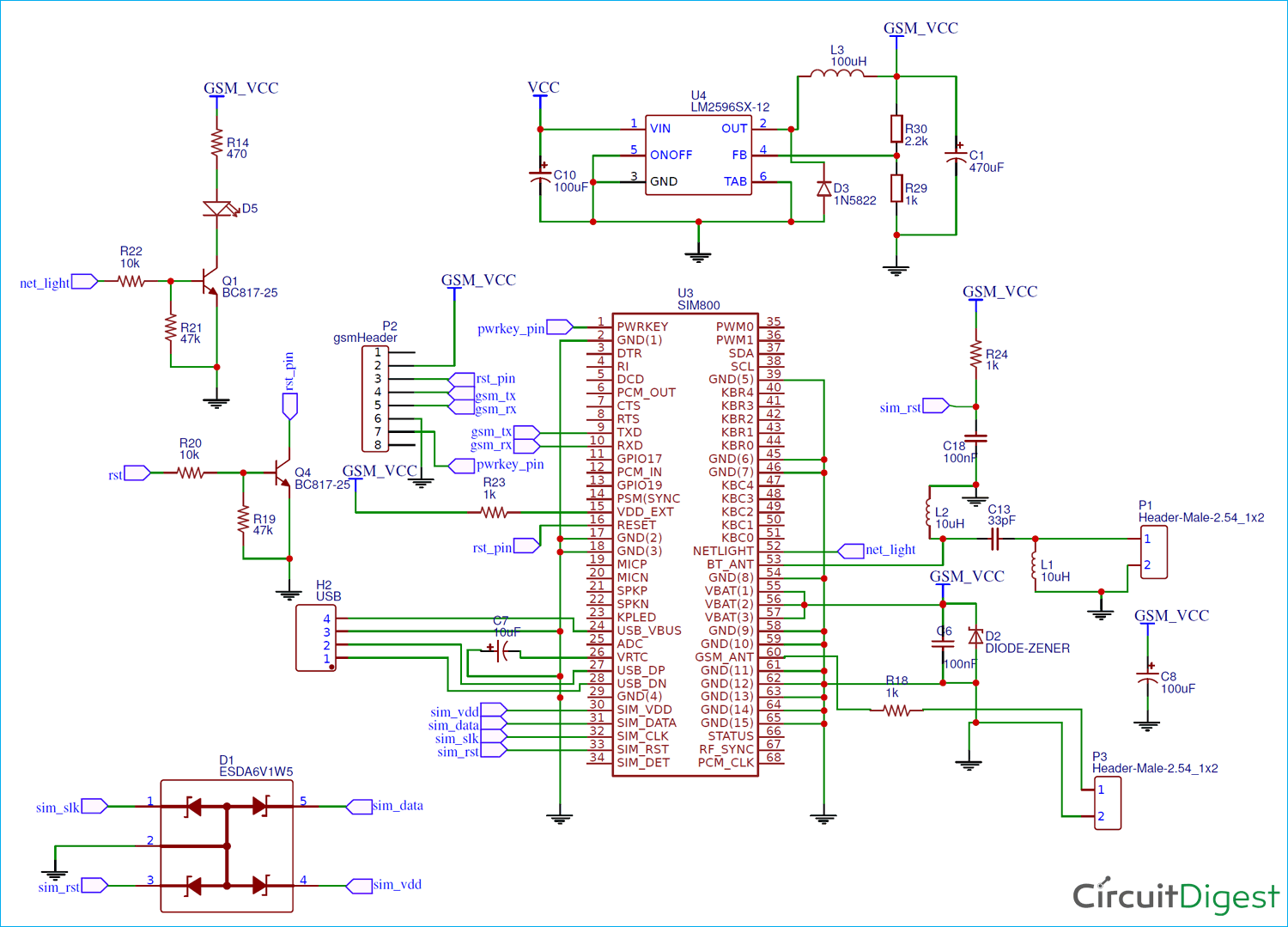
Two of them are from the coil where the input to drive the relay is supposed to be given. A fixed 12v voltage regulator gives power to arduino gsm modem and relay.
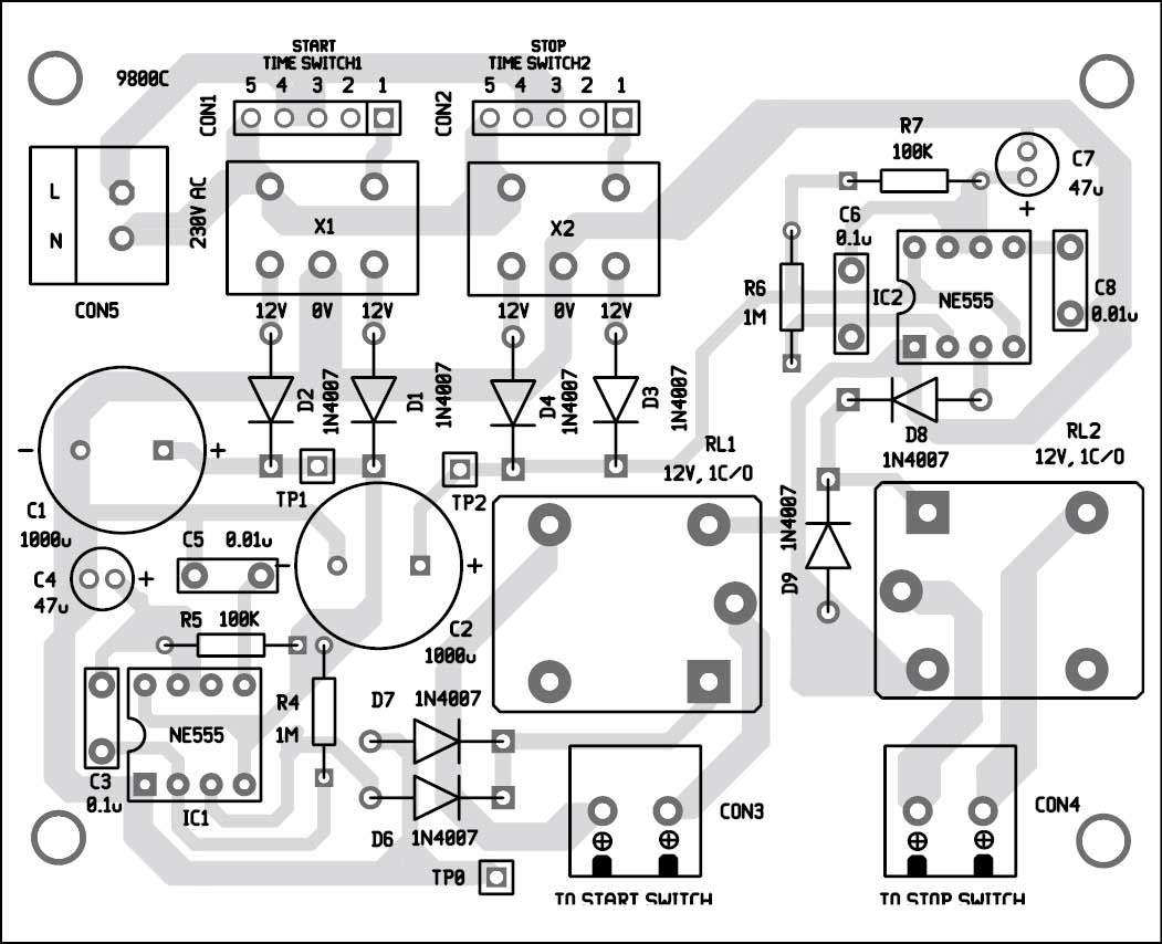
3 Phase Motor Programmable Controller Full Electronics Project
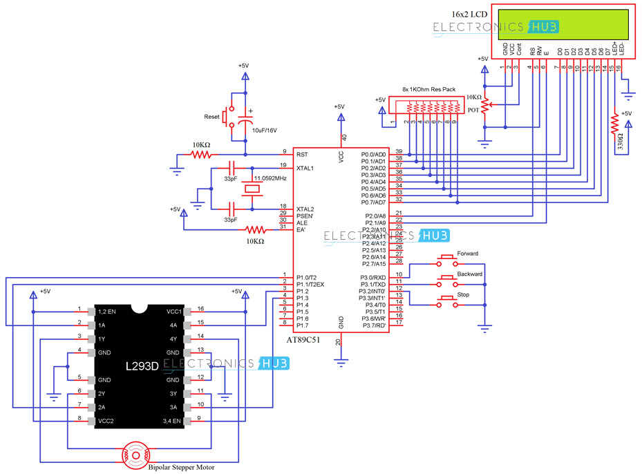
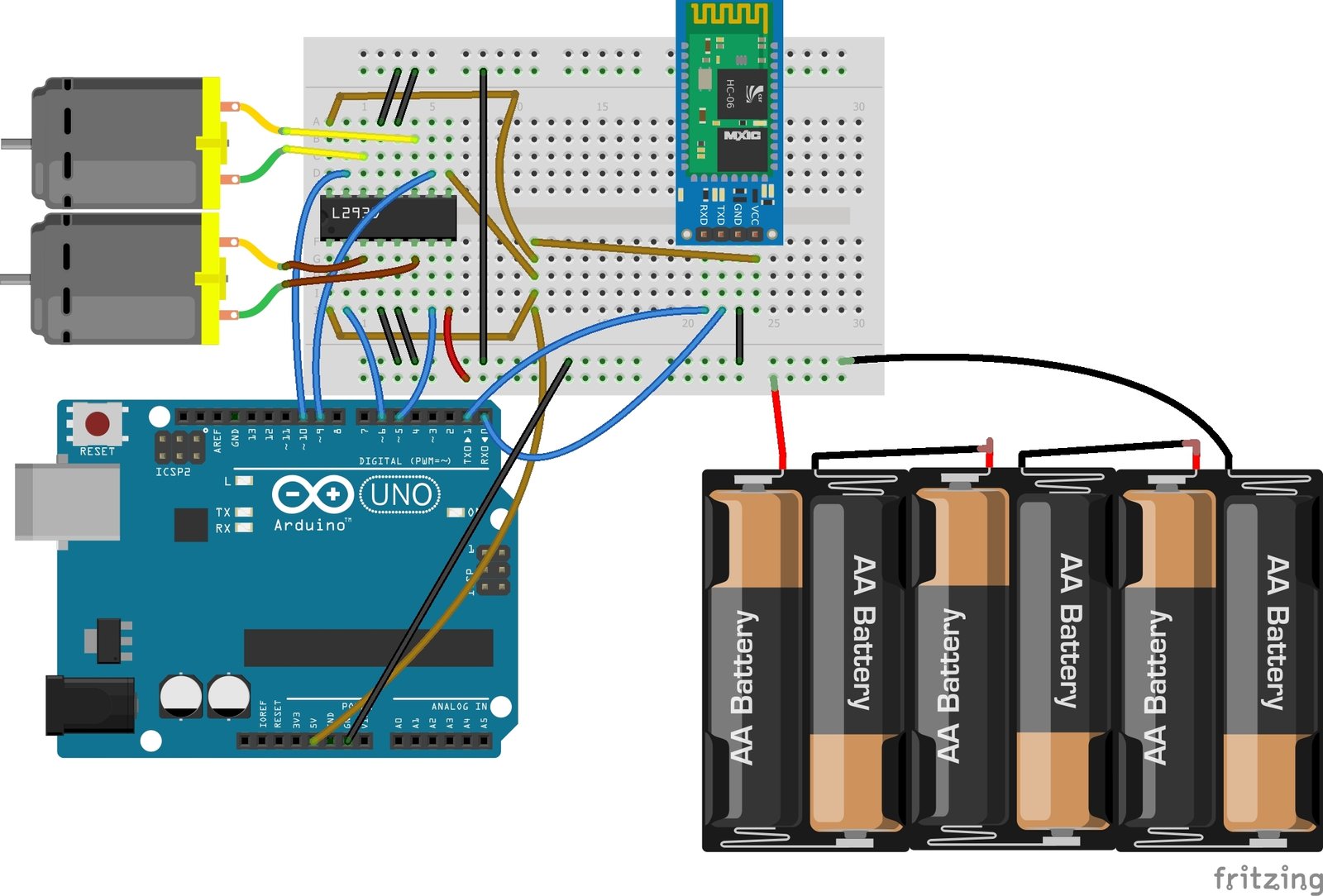
Gsm motor starter circuit diagram. Other devices for disconnecting and short circuit protection may be needed typically a circuit breaker or fuses. Assortment of 3 phase motor starter wiring diagram pdf. Lever mounted on the front of the switch. The above shown diagram is of a spdt single pole double throw relay. The rx of gsm is connected to tx of arduino and tx of gsm is connected to rx of arduino. The circuit can be modified in many different ways as per the users specifications.
Gsm pump controller mobile motor starter. The modem cell phone should be appropriately assigned with a particular continuous ringtone while the default ringtone should be assigned to empty tis will make the unit immune to unknown numbers or wrong numbers and the owner will be the sole controller of the attached circuit and the motors. The motor starter must have at least two components to operate. Controlling motor with a cell phone circuit diagram explained gsm based cell phone remote control switch circuit electronic cheap cellphone controlled water pump circuit for farmers 3 phase motor starter automatic mobile starter mobile starter gsm based remote motor controller and status. Circuit diagram showing nc connection of spdt relay. It consists of 5 terminals.
It shows the parts of the circuit as simplified shapes and also the power and also signal links in between the tools. Please refer to the manufacturers literature if in doubt. The gsm modem is connected to arduino at pin 0 and pin 1 which are rx and tx respectively. If you are not sure of how to make the connections on your equipment hire an electrician. Your motor starter may use wiring which is internal to the starter wiring which is different than the diagrams etc. All diagrams are intended to illustrate the logic of a latching contol circuit.
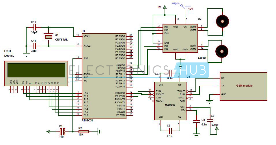
A wiring diagram is a streamlined conventional photographic representation of an electrical circuit. The other three are no normally open nc normally closed and com common. The gsm based motor control circuit consists of a gsm modem for sending and receiving sms an arduino board will interpret the received sms command and gives out control signal to l298n dc motor driver which drives the motor at the desired speed and direction. If you are confused just look at the below diagram misconnection will not send or receive sms. A contactor to open or close the flow of energy to the motor and an overload relay to protect the motor against thermal overload. Wiring diagrams do not show the operating mechanism since it is not electrically controlled.
In gsm based the gsm pump controllers mobile pump starter are specifically design to operate remote located submersible pumps and motors for benefit of farmers agriculture people and industries where wireless pump and motor control required. These motor starters consist of an on off snap switch combined with a thermal overload device operating on the eutectic alloy ratchet principle.
