Day by day the price of the solar panel falls gradually. Solar garden light circuit diagram.

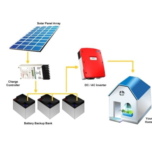
What Is Standalone Solar Electric System Electrical4u
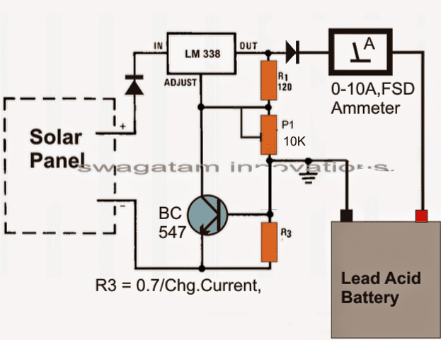
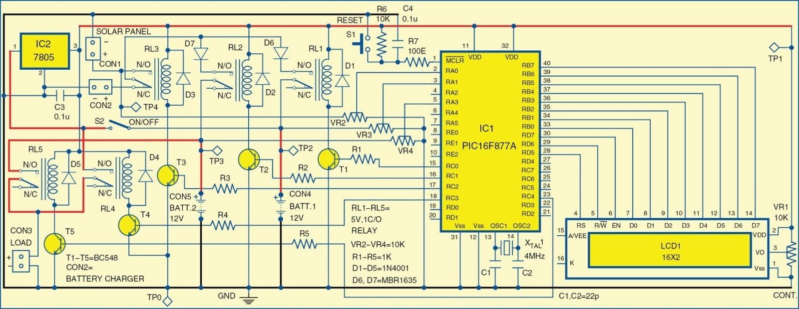
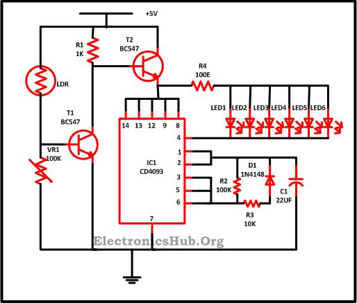
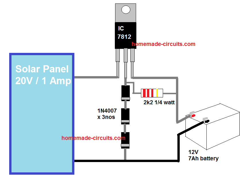
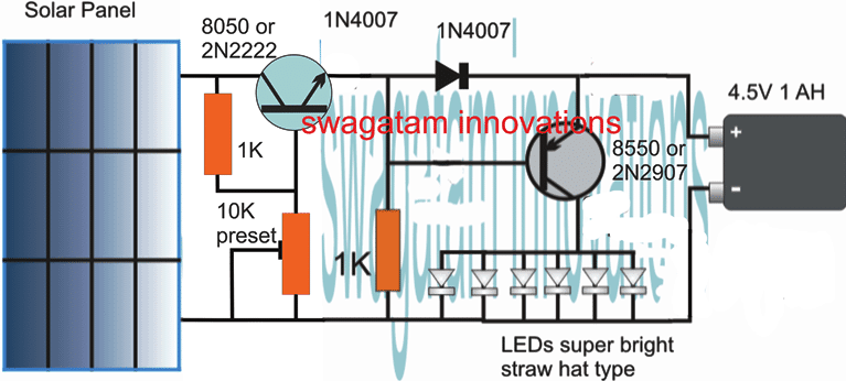
Solar home lighting system circuit diagram. This circuit is a little different than the circuits that use the solar cell for a dark detection. N channel mosfet q2 irf540n is used for charge controlling operation. Circuit diagram of solar garden light. As can be seen in the given circuit diagram the design basically consists of a solar panel a pnp transistor few leds a battery and a few resistors. You could utilize 3 100 watt panels listed below. Solar lighting system circuit.
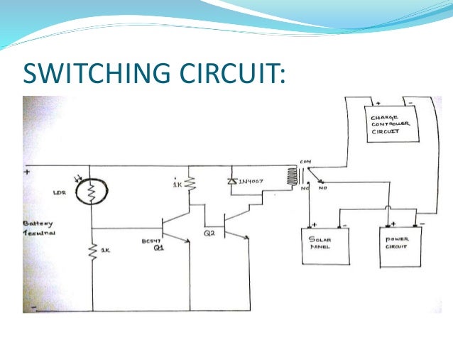
The solar garden light circuit will consist of two parts. This circuit uses a photo resistor for the dark sensor in place of the solar cell. Now the diode is placed right after the solar cell so q1 and q2 are powered by the battery. A basic solar power system without going into great detail i thought that i would illustrate a very simple and basic solar power system diagram. So i write this instructable to get all the components of your solar system separately and assemble it all by yourself. Heres a simple small 300 watt solar panel system with a 600 watt dc ac inverter just for an example.
Pir solar home lighting circuit last updated on july 3 2019 by swagatam 15 comments the post explains a simple circuit using passive infrared or pir for making an automatic solar led lamp which can be used for illuminating your home automatically at sunset and only in the presence of a human member in the premise. Diy off grid solar system. When sunlight falls on the solar cell during daytime the solar cell charges the rechargeable battery and turns led1 off. But still installation of a complete off grid solar system is costly. The dc voltage from the solar panel is used to charge the battery and control the relay. This circuit requires only a single ni cd rechargeable battery to light up the white led for more than five hours depending upon the ampere hour ah capacity of the battery.
One is charging and the other one is to control the leds. Solar cells generate direct current so make sure that dpdt switch s1 is towards the solar panel side. The complete circuit diagram is explained as two parts the first part is given below. Potentiometer r1 is used to set the. According to the specs of these particular. Gama sonic prairie bulb single black integrated led outdoor solar post light with 3 mounting options fitter pier and wall mounts model gs 114b fpw blk 71.
Capacitor c1 connected in parallel with a 12v relay coil remains charged in daytime until the relay is activated. The transistor is the only active component which is positioned as a switch for preventing the battery voltage from reaching the connected leds during day time.

