The hot wire from the source connects to the. Yeah also several electrical wiring representations are offered this wiring layout can take the reader heart a lot.

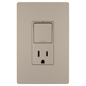
Radiant Combination Tamper Resistant 15a Self Test Single
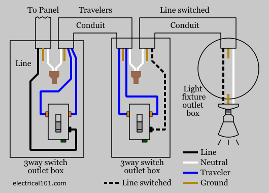
Legrand switch outlet combo wiring diagram. Wiring diagram 3 way switch with light at the end. The source is at sw1 and 3 wire cable runs between all the devices. They can work in conjunction with one another or they can be connected and used independent of each other. The source hot wire is spliced with one of the switch wires and the other switch wire is connected to the hot line terminal on the device. To wire the outlet you need a white neu wire to wire to the silver wire. The source neutral is connected the line neutral terminal.
With this wiring the receptacle can be controlled from two locations. Dear visitors when you are searching the brand new switch receptacle combo wiring diagram circuitry diagram collection to read this day switch receptacle combo wiring diagram can be your referred electrical wiring representation. This diagram shows the wiring arrangement for a 3 way switched outlet. I confirm that the user guide included in the box describes with a clear diagram your setup with three way control and permanent outlet so it will support it. 3 way switched outlet wiring diagram. Wiring diagram for a switched gfci combo outlet.
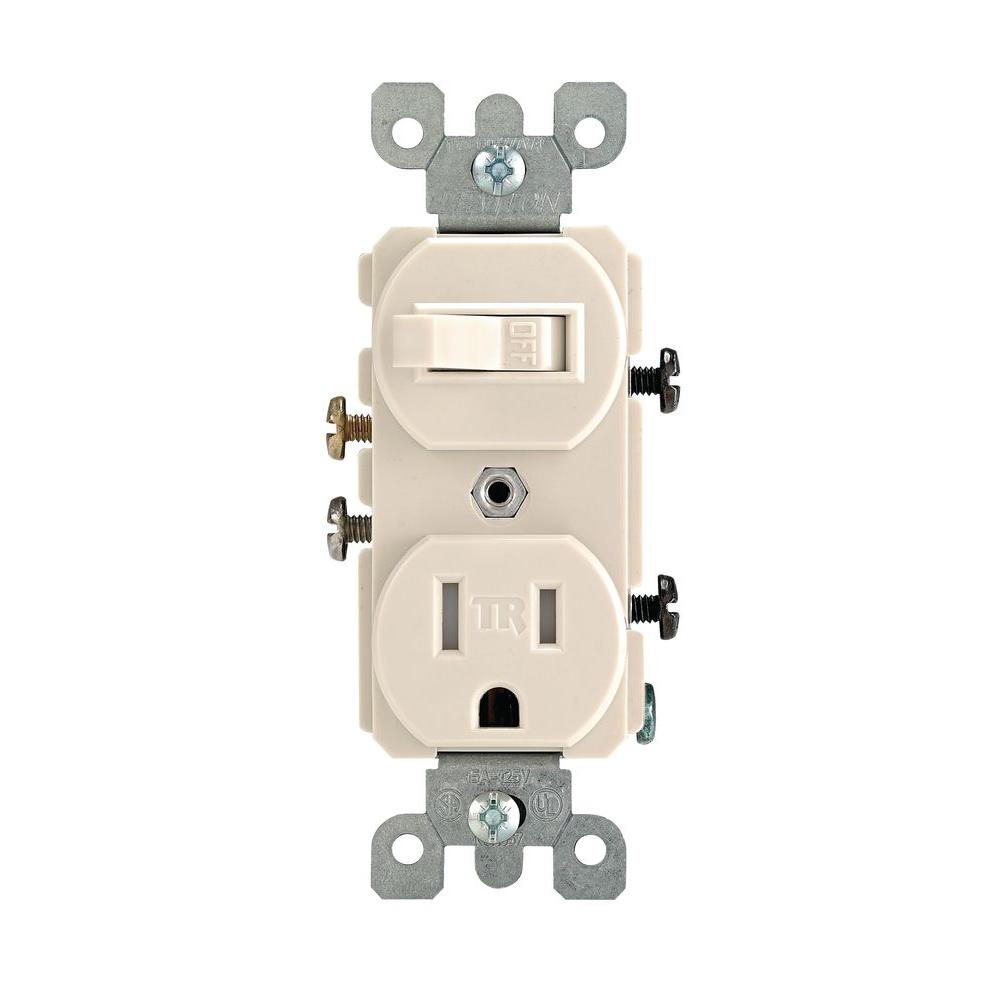
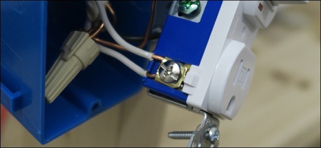
I just bought this switchoutlet for my coffee machine to have a switchable outlet rather than unplug it all the time since the coffee machine doesnt have a power button. Wire hot black wire or red on the brass screw on the side where the two screw is tie together and the other black ore red wire to the brass screw on the side where you see a silver screw on the same side. The existing switch has two black screws and no ground screw. Also hook the bare or green wire on the green screw. Combination switch and outlet combination electrical question. The switchreceptacle combo device is set up like a duplex receptacle but has a 15a single pole switch in one half and a single 15a 125v receptacle in the other half.
The new device is a cooper wiring 274w box combination device with a switch pilot light and an outlet. I would like to replace a single light switch with a combination switch with pilot light and outlet. To have the switch control the power to the outlet you need to connect the wire as follows using the 2 black leads from the switch. In this diagram the switch built into the combo device is wired to control the gfci outlet itself. One black lead to hot from breaker one black lead to hot terminal line side of gfci white neutral wires get connected to silver terminal on line side of gfci.
