5 hp electric motor single phase wiring diagram beautiful single. Ultimate nintendo switch hacpaaaba.

0d6f Magnetic Motor Starter Wiring Diagram For Compressor
Air compressor motor starter wiring diagram. Air compressor motor troubleshooting part 1 bad start capacitor switch. We have a. How to wire a single phase compressor motor starter. Assortment of air compressor motor starter wiring diagram. Both of these are optional and may not be present in all applications. Wiring a 3 phase motor for an air compressor.
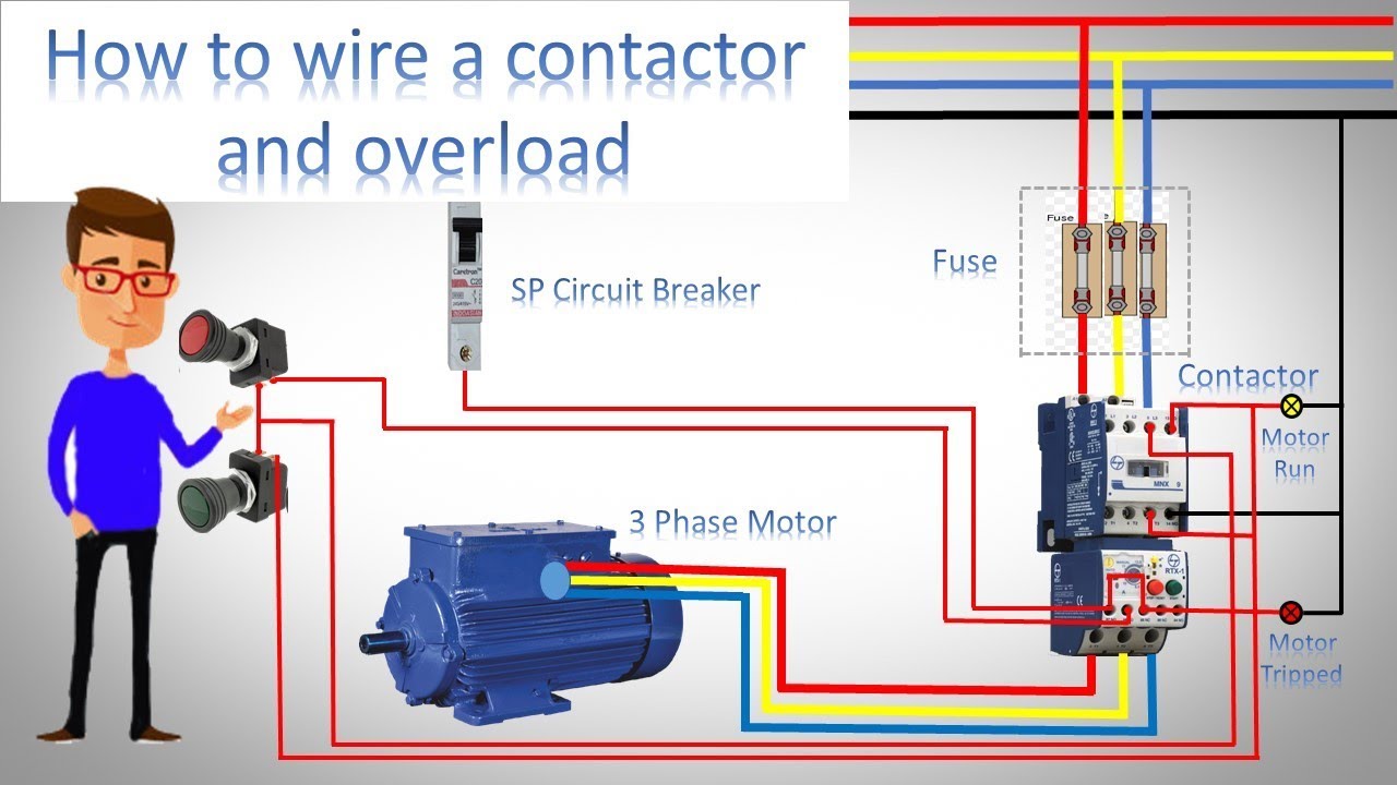
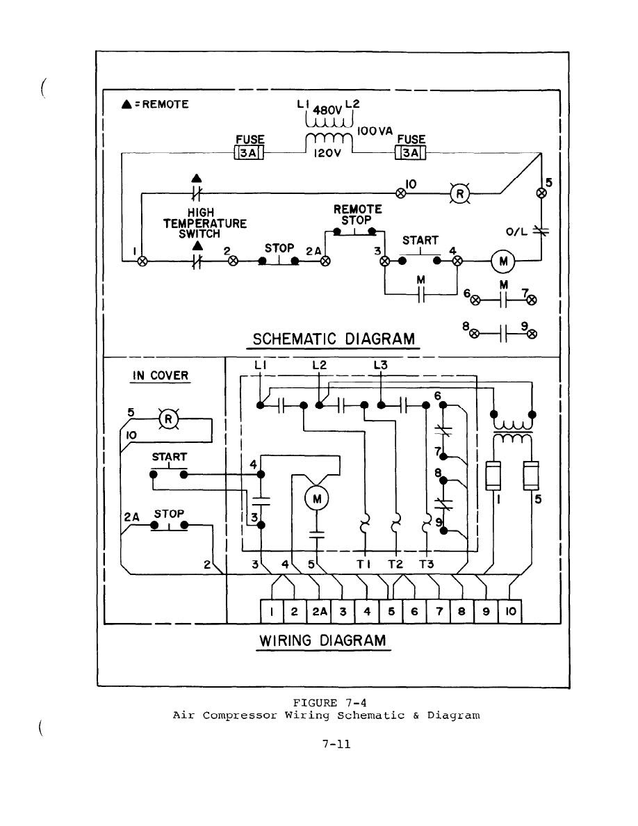
Includes autohandoff control and low oil switch nc. Line voltage control three phase 3ph motor starter controlling a three phase motor rev 08 aug 2006 the above wiring diagram assumes your magnetic starter has a 240v coil. Of the starter pressure switch compressor base magnetic starter motor connect power to the magnetic starter through the knock out plug in the top of the starter the magnetic starter is a large relay that switches high current from the main power line in response to a sig nal from the pressure switch. Air compressor magnetic starter wiring duration. Before you wire a 230v air compressor you should always check the manual for the proper wire gauge. Baldor reliance industrial motor wiring diagram new wirh baldor.
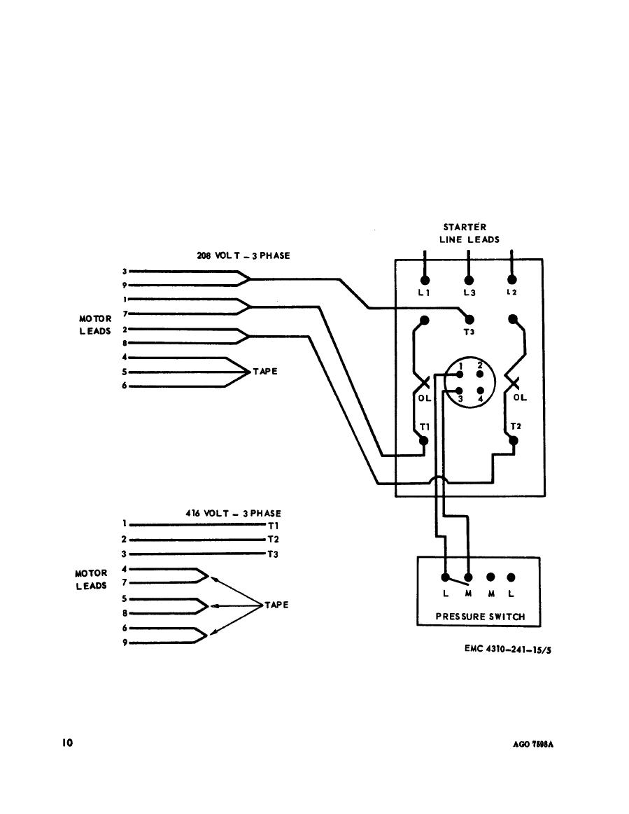
Typical motor starter applications include a control circuit which. All 230v appliances must be connected to a dedicated circuit powered by a double pole circuit breaker with the proper amperage rating. In some cases the switch will include only autooff. The wiring procedure may or may not call for a neutral wire. Fig 4 illustrates how to wire the magnetic starter to the motor and pressure switch for further information on magnetic starters refer to form 200 1946 warning. Shut off the main power.
A wiring diagram is a simplified standard photographic depiction of an electric circuit. Baldor single phase motor wiring diagram collections of weg motor capacitor wiring diagrams schematics and baldor diagram in. Tm 5 3895 374 24 1 installing the magnetic starter this air compressor requires a magnetic starter to prevent motor damage in the event of a thermal overload. This video is by a common request that goes over a basic wiring diagram for a magnetic starter used for a 2 stage air compressor application. Weg motor capacitor wiring diagrams schematics and baldor diagram in. This video is intended for information use only with.
When changing the voltage of the motor be sure to see the wiring diagram on the motor label and make sure of the circuit voltage which is supplied to the motor matches one of the optional voltage configurations of the motor. The national electric code and local codes. Air compressor or float pump3ph starter1ph motor line voltage control magnetic starter controlled by a air compressor pressure switch nc. The wood craftsman 49057 views. Ladder diagram basics 3 2 wire 3 wire motor control circuit duration. It shows the components of the circuit as simplified shapes and also the power and signal connections in between the tools.
Gallery of Air Compressor Motor Starter Wiring Diagram