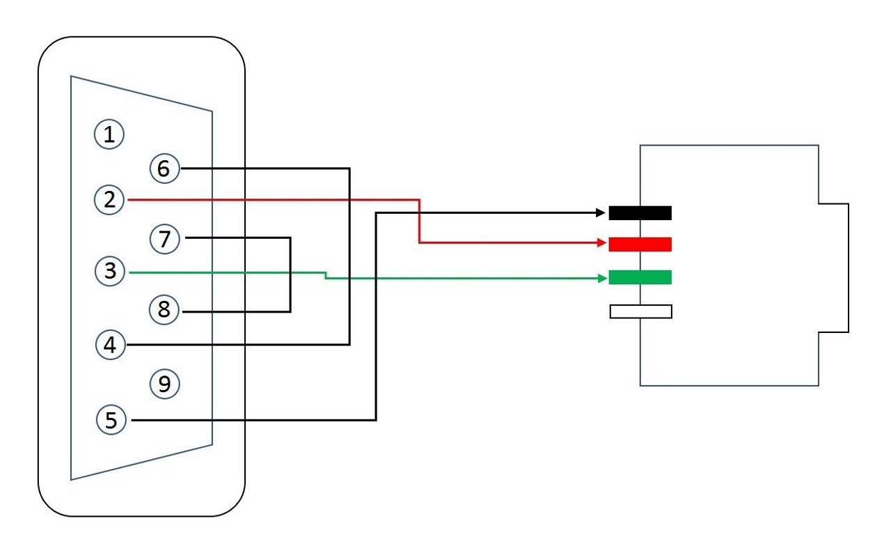
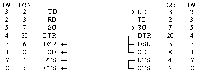
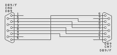
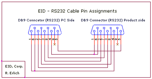
What is an rs232 9 pin pinout. Db 9 and db 25 connection.
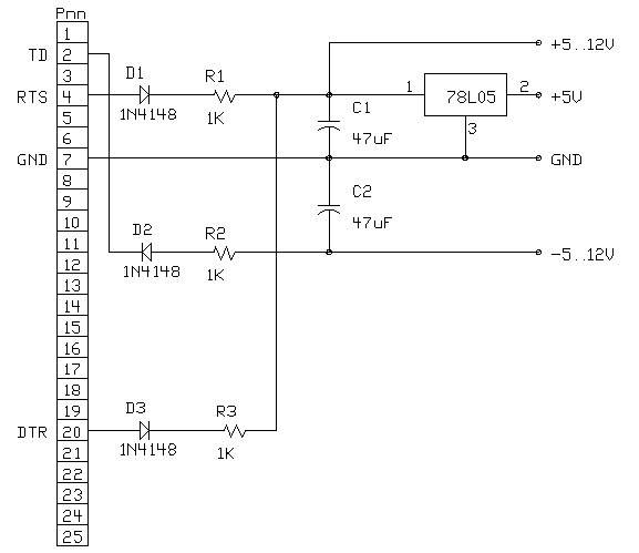
How To Get Power From Rs 232 Port
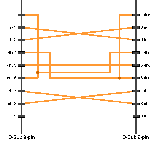
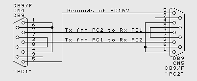
Rs232 connection diagram. The most common null modem cable types are shown here. An rs232 pinout 9 pin cable features nine pins. For a windows 9598me direct cable connection the rs232 null modem cable with loop back handshaking is a good choice. Connecting two pcs together using rs232 without handshaking when handshaking is required generally rts of one device connects to cts of the other and vice versa and also dsr of one device connects to dtr of the other device and vice versa. These cable can take a variety of forms in terms of the physical methods used for construction as well as the number of connections that are incorporated within the overall rs232 cable. Use a cable wired as shown in the diagrams below.
A computers serial com port dte is usually a male port as shown below and any peripheral devices you connect to this port usually has a female connector dce. It can also connect device to a power supply for charging purpose. In telecommunications rs 232 recommended standard 232 is a standard originally introduced in 1960 for serial communication transmission of data. However wireless designer can connect to a receiver frame over a pcs rs232 port as well. The diagram below indicates how you would go about connecting two pcs together without handshaking. In order to link these devices an rs232 d9 pinout is essential as this pinout will allow you to connect two devices successfully.
Most of them use usb cable. Dr receiver has db9 connector on rear panel venue receiver has 35mm trs jack on rear panel. Whenever rs232 is used rs232 cables will be needed to provide the required electrical connection. Rs232 null modem cables with handshaking can be defined in numerous ways with loop back handshaking to each pc or complete handshaking between the two systems. It formally defines signals connecting between a dte data terminal equipment such as a computer terminal and a dce data circuit terminating equipment or data communication equipment such as a modemthe standard defines the electrical. Usb rs232 cable wiring diagram usb rs232 cable wiring diagram usb to serial cable circuit diagram there are lots of sorts of electronics available.
In this pin out provisions were made for a secondary communication channel. The cable may be utilized to transfer information from one apparatus to another. Rs232 monitoring hardware establishes a connection between data terminal equipment dte and data communication equipment dce. In practice only one communication channel with accompanying handshaking is present. Rs232 cable wiring diagrams normally the rs232 port is used by touch panel controllers and similar devices. The original pin layout for rs232 was developed for a 25 pins d sub connector.
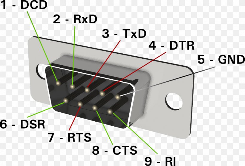
Rs232 pinout below is the pinout of a typical standard male 9 pin rs232 connector this connector type is also referred to as a db9 connector. For that reason the smaller 9 pin version is more commonly used today. This little gizmo well does what its call it converts a 9 pin d type rs232 connector to a 25 pin d type rs232 connector. There one more thing to add here about rs232 wiring and thats the 9 pin to 25 pin converter connection.


