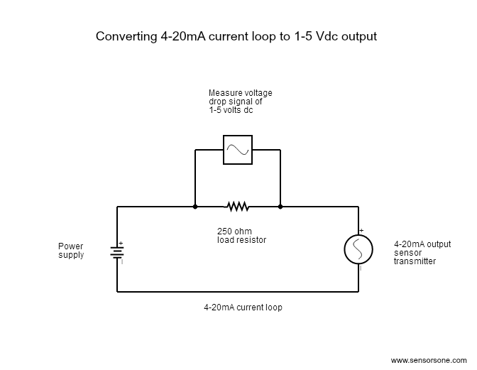
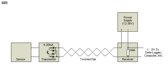
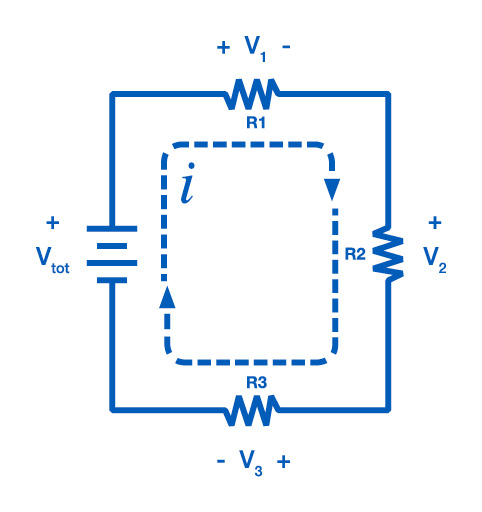
In addition to an adequate vdc supply there also needs to be a loop which refers to the actual wire connecting the sensor to the device receiving the 4 20 ma signal and then back to the transmitter. Removal of the entire 751 device from the series configuration will disrupt the loop.

Need More Current Than 4 Ma In 4 20ma Loop Current
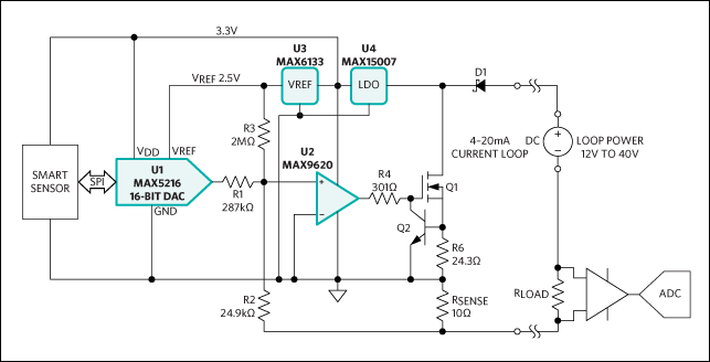
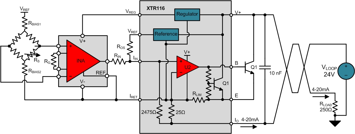
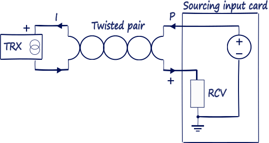
Loop powered transmitter wiring diagram. The industrial io experts with over 60 years of experience. An additional cable core is required for each transmitter compared to current sink and source options. 2 wire loop powered transmitter current loops. The current signal on the loop is regulated by the transmitter according to the sensors measurement. The receiver at maximum current plus the voltage drop in the wiring and all the while maintaining the minimum voltage required by the transmitter to maintain operation. All 4 20 ma current loops require a power supply in order to operate.
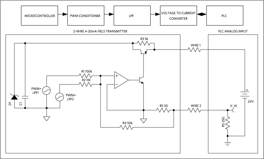
This configuration supplies power and 4 20ma signal over a two wire loop connection between the transmitter and the control panel. A loop powered transmitter connects to a process controller with only two wires which is why loop powered transmitters are synonymously known as 2 wire transmitters. Depending on the source of current for the loop receiver devices may be classified as active supplying power or passive relying on loop power. A if the 4 20ma input device includes an internal sensor power supply and has 2 input connections. Connect negative input connection to negative pressure transmitter connection. A separate power supply is required for both the transmitter and control panel.
Loop powered devices are often much lower cost than other process control devices with built in high power electronics. Connect positive input connection to positive pressure transmitter connection. 2 3 and 4 wire loops in their vary basics. The 751 is designed so the analog or lcd display can be removed from the housing without impacting the integrity of the 4 20 ma loop. Two wire 4 20ma loops loop powered device. It is possible to convey electrical power and communicate analog information over the same two wires using 4 to 20 milliamps dc if we design the transmitter to be loop powered.
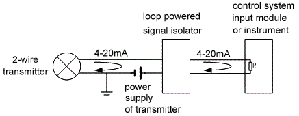
Description and wiring examples. This is a typical wiring diagram of a loop powered signal isolator get energy from the input and 4 wire transmitter detailed parameters of loop powered signal isolator ato s sinir 502e are in the product page. Transmitter does not contain a test terminal. A lot of loop setups will utilize an external power supply in order to power the devices which are attached to the current loop. Two wire loop powered transmitters. Wiring diagram of loop powered isolator with external powered 4 wire transmitter.
Rosemount 751 series wiring diagrams. B if the 4 20ma input device requires an external sensor power supply and has 2 input connections. Acromag is an international corporation that combines more than 60 years of process monitoring and control experience with a solid background in high tech computer design. This is simply because the expensive components that could be included in these devices such as power supplies mechanical relays or advanced digital or analog signal output components are omitted in order to limit the amount of power necessary to operate the device.

