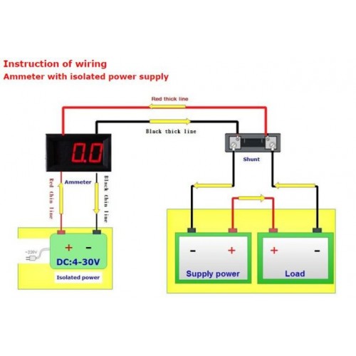
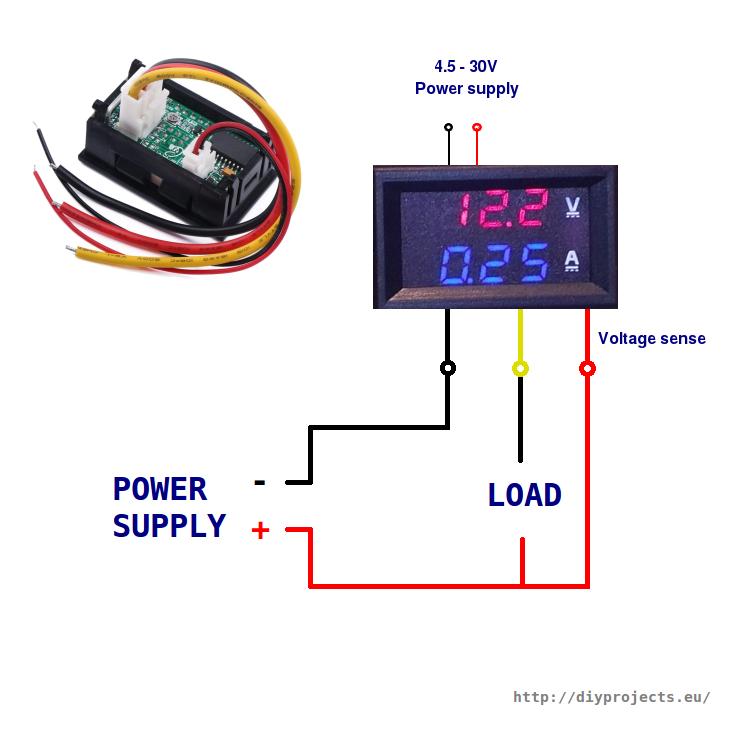
There is a connector with thick wires and connector with thin wires. They are basically the same.

Diagram Based Aircraft Ammeter Shunt Wiring Diagram
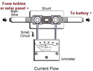
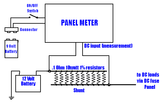
Amp meter shunt wiring diagram. For example a 50 amp50mv meter requires a 50 amp shunt. Then locate any wire that has power with the ignition off. A 200 amp50mv meter requires a 200 amp shunt. It looks for the current drop across a resistor shunt and uses that instead of a direct current measurement. It is useful to think of water flow in a pipe when thinking about current flow in a wire. Assortment of volt amp meter wiring diagram.
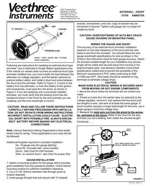
The main power goes from the battery to one side of the shunt via a 12 gauge red wire and then from the other side of the shunt to the horn relay via a 12 gauge black wire. Use the wiring diagram and test light or multi meter to locate the positive wire from the alternator to the fuse block. In the diagram above the wire colours shown in brackets refer to model tc0002. 48mm x 29mm x 21mm. I want to use a 24 vdc amp meter for my elect train layout the problem im. Dc 0 100v 10a digital voltmeter ammeter dual display 10a voltage detector current meter panel amp volt gauge 028 red blue led features.
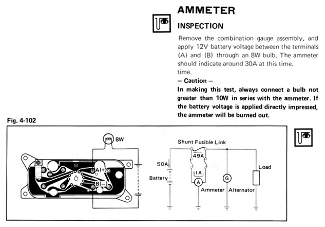
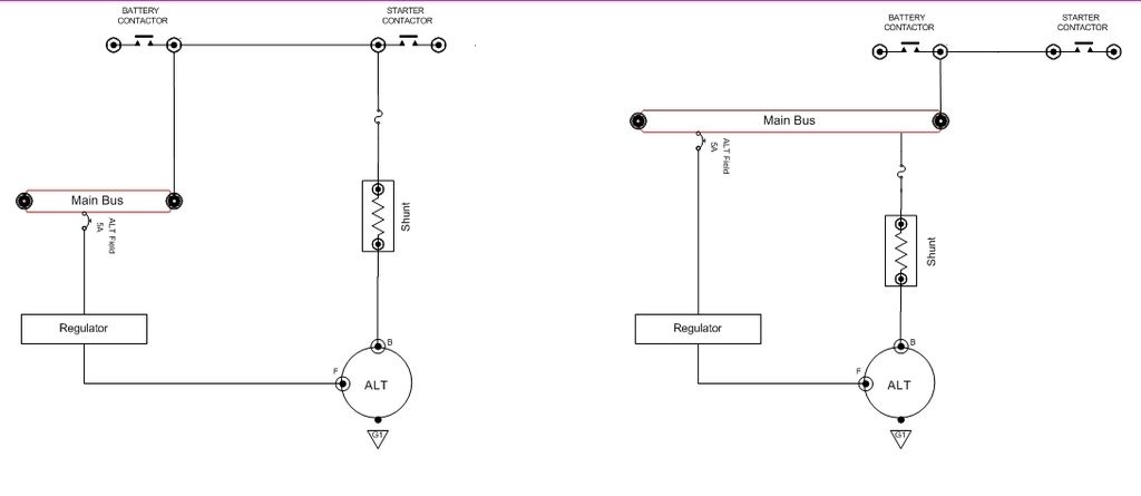
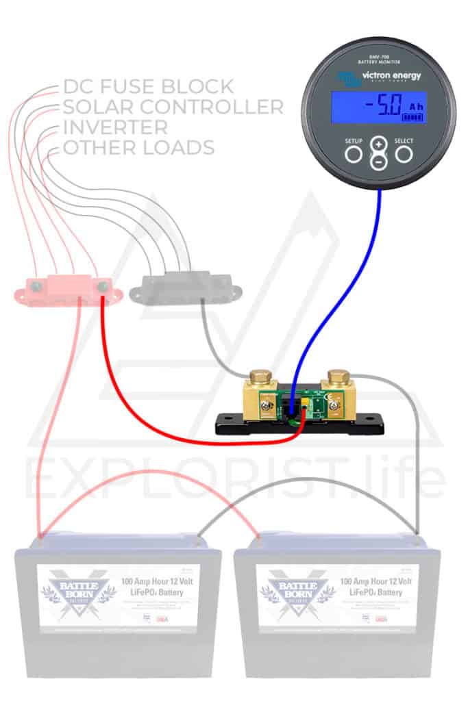
Blue sea systems meters read full scale deflection at 50mv. The shunt connects in parallel to the ammeter because of which the voltage drops across the meter and shunt remain the same. Here is the original ss wiring diagram. The circuit has ammeter and shunt which is connected parallel to each other. It reveals the elements of the circuit as simplified forms and the power and signal connections between the devices. In this video i show how to properly wire an ammeter amp gauge with a shunt to measure amps.
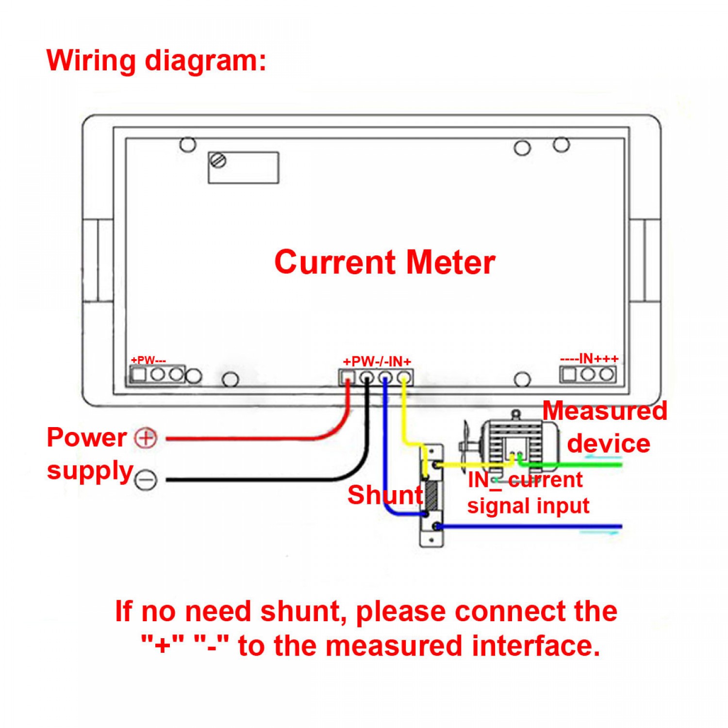
Also when measuring current that exceeds 10a which can be handled with the internal one. A wiring diagram is a simplified traditional photographic representation of an electric circuit. As you can see from the diagram both modules have 5 wire leads 2 for connection to meter power which must be in the range of 45 to 30v 2 for connection to the current shunt measuring terminals and 1 for the voltage measuring wire. Ill show you how. Consider the circuit used for measuring the current i. Thus the movement of the pointer is not affected by the shunt.
Shunts and meters must be matched by their ratings and calibration. Use the flashlight or drop light to see the wiring under the dash. How a shunt works. You need a wiring diagram with an external shunt instead. Bought an ammeter and shunt from china with no instructions how to wire it.
