The motor draws more current and it runs more efficiently at 220 230 or 240 volts than 120 volts. It shows the elements of the circuit as simplified shapes as well as the power and signal links in between the devices.

Rigid Air Compressor Wiring Diagram H1 Wiring Diagram
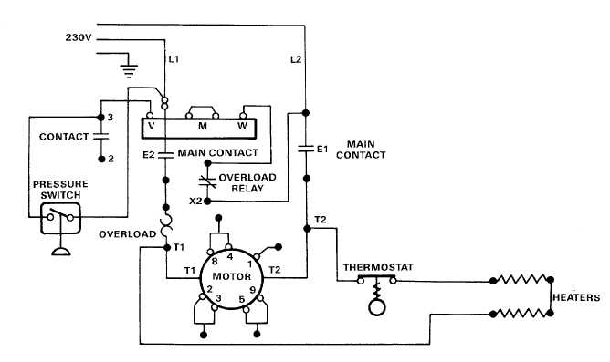
Air compressor motor wiring diagram. Basic pressure switch wiring. Assortment of wiring diagram for air compressor motor. Each part ought to be set and linked to other parts in particular way. It reveals the elements of the circuit as simplified shapes and the power and signal links between the devices. A wiring diagram is a streamlined conventional pictorial depiction of an electric circuit. In this video jamie shows you how to read a wiring diagram and the basics of hooking up an electric air compressor motor.
These voltage ratings are essentially equivalent so the procedure for wiring a 220 volt compressor is identical to that for wiring a 230v or 240v one. Kill the power to the compressor completely when you are wiring a compressor pressure switch. Air compressor motor troubleshooting part 1 bad start capacitor switch. Assortment of air compressor motor starter wiring diagram. The air compressor users manual will specify the required power source. For the typical diy type home or small workshop air compressor that power supply is a plug on a wire that connects to a wall socket.
Circuit size for an air compressor the circuit size will depend on the size of the air compressor and the horsepower rating of the motor. Every motor should have a name plate which is typically attached on the side or end of the motor. The information found on the label tells all about the motor size and electrical requirements. It has a larger tank and a larger more powerful motor to fill it. It shows the components of the circuit as simplified shapes and also the power and signal connections in between the tools. The basic requirements for wiring electric motors.
Ultimate nintendo switch hacpaaaba. You have a power supply to the air compressor. Line voltage control three phase 3ph motor starter controlling a three phase motor rev 08 aug 2006 the above wiring diagram assumes your magnetic starter has a 240v coil. Wiring diagram for sanborn air compressor. These tips can be used on most electric motor brands such as weg baldor. Circuit wiring for a 240 volt air compressor.
A dedicated circuit will be required for most larger air compressors. A wiring diagram is a simplified standard photographic depiction of an electric circuit. Variety of air compressor wiring diagram 230v 1 phase. Thanks for your electrical wiring question cody. A wiring diagram is a simplified traditional photographic depiction of an electric circuit. Wiring a 3 phase motor for an air compressor.
If not the structure will not function as it should be. Air compressor wiring diagram 240v air compressor wiring diagram 240v every electric structure is composed of various diverse components. How to wire a single phase compressor motor starter.
Gallery of Air Compressor Motor Wiring Diagram


.jpg)