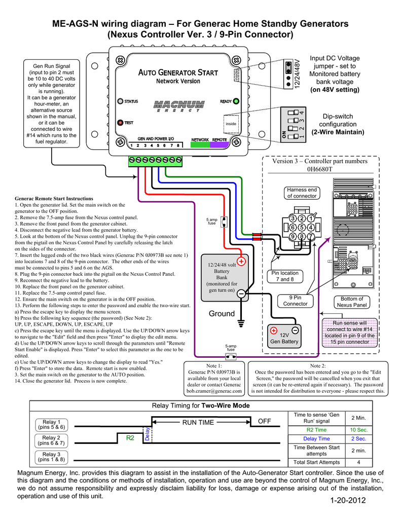
Newer homes may have 4 prong 125250v drier outlet nema 14 30r. A wiring diagram is a streamlined traditional photographic depiction of an electric circuit.

Generator Wiring Diagram To The Home Supply System
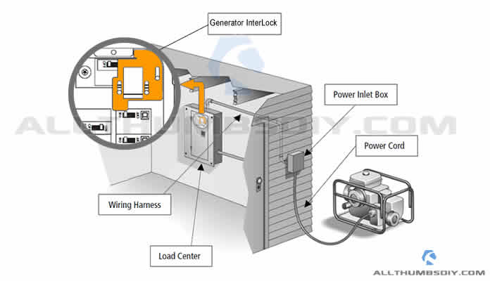
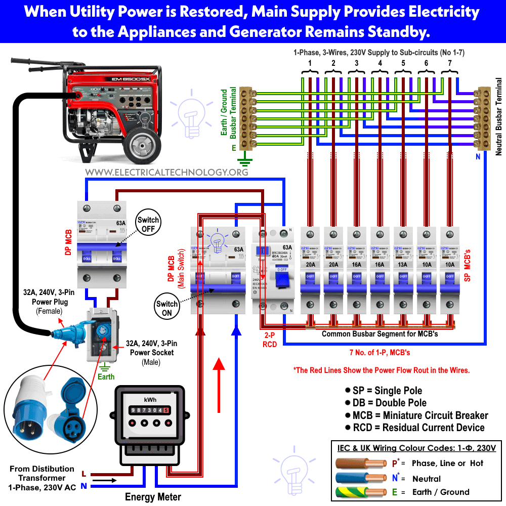
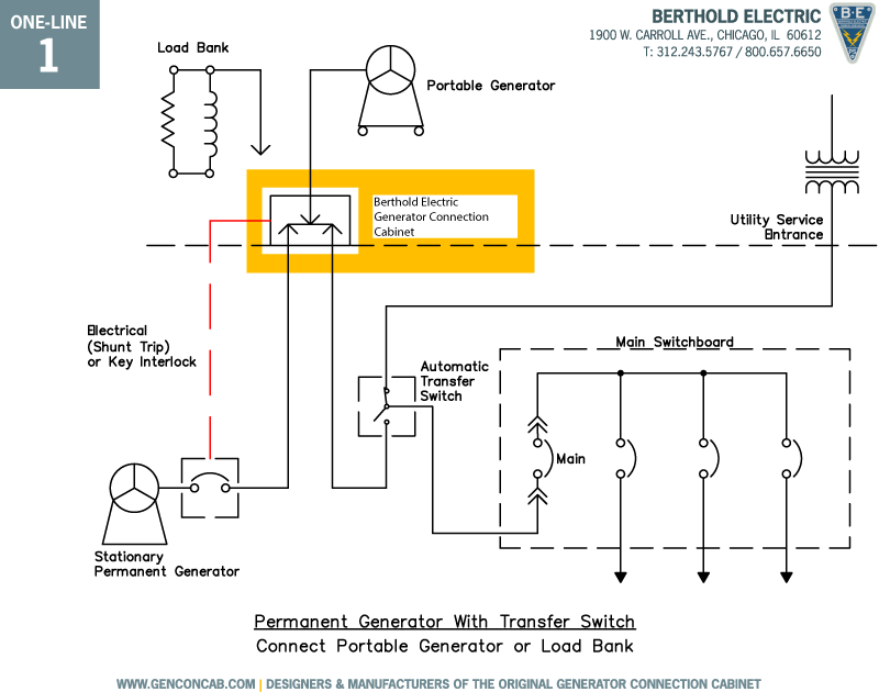
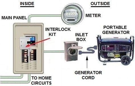
Generator panel wiring diagram. Installing a generator interlock involves working inside the load center aka. There are three main types. A generator transfer switch is the legal and proper way to power your home with an emergency generator. If utility power fails the switch connects the generators power to the circuits in the generator sub panel. Connecting the current transformers after the mains and generator changeover will allow you to read and monitor the current when the load is connected to the power utility. The above illustrated diesel generator control panel wiring diagram is the typical connection wiring diagram of the bek3 automatic mains failure controller.
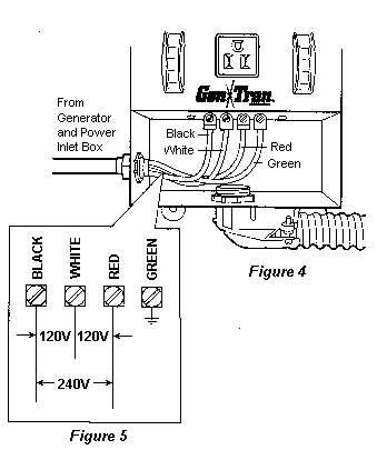
It provides a separate ground hole besides l1 l2 and n see diagram. It reveals the components of the circuit as streamlined forms as well as the power as well as signal connections between the gadgets. Each has varying degrees of complexity benefits and expense. Automatic manual transfer sub panel and a breaker interlock. For our task it has the right number of leads but a wrong geometry. Wiring a generator 4 prong cable to 4 prong outlet.
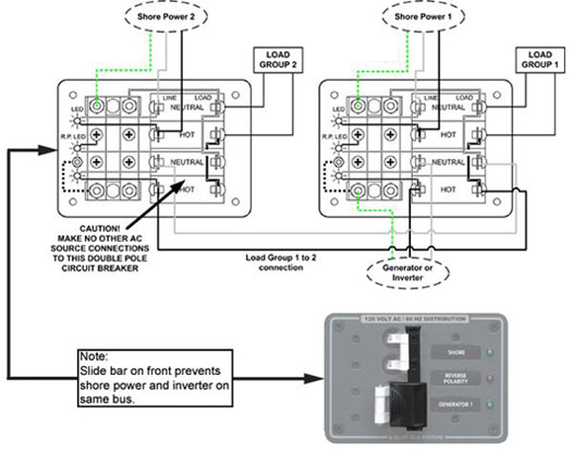
Touching them directly conductors or indirectly lug nuts will result in serious injury or death so extreme caution is. You need to remember that when you turn off the main breaker conductors aka. When utility power is functioning the wires from the circuit breaker in the main electrical distribution panel are connected to the generator sub panel. Figure 5 wiring diagram of a manual transfer switch in the on position. Variety of generator control panel wiring diagram. Cables or legs from the outside meter will remain hot or energized.
