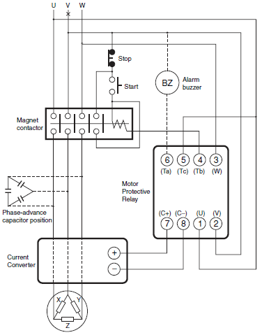
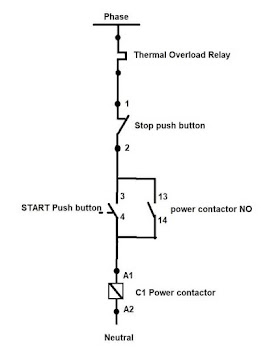
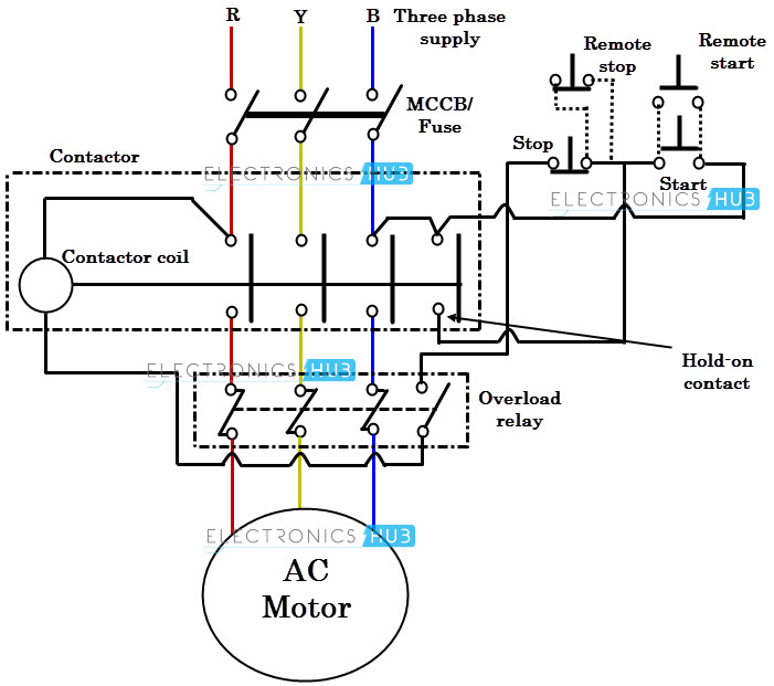
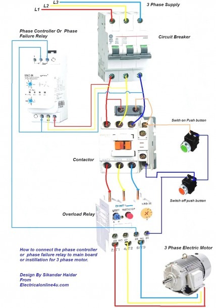
Dol starter control and power wiring by using a fuse contactor overload relay motor. Additional resources e300 electronic overload relay installation instructions publication 193 in080 provides complete user information for the e300.

Af Contactors 3 Pole Contactors And Overload Relays For
Overload relay connection diagram pdf. Overload relays are designed to imitate on a much smaller scale the heating patterns of the electric motor it is installed in and interrupt the current once the heat sensing mechanism in the relay reaches a certain temperature. A relay type b relay range c max. Thermal overload relays for use with unbalanced loads classes 10 a 1 for connection by btr screw connectors 2 and control by spring terminals in the references selected above replace lrd3 with lr3d3. Wiring diagram book a1 15 b1 b2 16 18 b3 a2 b1 b3 15 supply voltage 16 18 l m h 2 levels b2 l1 f u 1 460 v f u 2 l2 l3 gnd h1 h3 h2 h4 f u 3 x1a f u 4 f u 5 x2a r power on optional x1 x2115 v 230 v h1 h3 h2 h4 optional connection electrostatically shielded transformer f. Fuse rating specified on every relay. An important characteristic feature of overload relays conforming to iecen 60947 4 1 are the tripping classes class.
To access this file click the attachments link the paper clip and double click the file. Overload test 1m 1m dut 1m 1m from current source nc contact of relay connections of thermal overload relay for ol testing testing of thermal overload relay 1. Access relay parameters the spreadsheet that is attached to this pdf details the e300 parameters. Overload relay 1ct m m motor 3ct to 120 v separate control ot is a. Overload relay connection diagram. An overload relay is made up of a heater paired with normally closed contacts that open once the heater gets too hot.
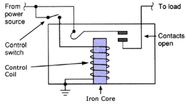
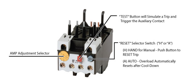
Although there are several types of overload relays available in the market however the most frequent type of relay is the. The overload relay workingfunction is discussed below. The wiring diagram of an overload relay is shown below and the connections of an overload relay symbol may seem like two opposite question marks otherwise like s symbol. In order to protect motors against short circuits it is advisable to use fuses am in conjunction with the thermal overload relay. Thermal overload relays for use on 1000 v supplies classes 10 a 1 for connection by screw clamp terminals. The specifications in relation to short circuit protection for contactors and overload relays.
3 pole overload relays should be so connected in the case of single phase and dc motors so that all three poles of the overload relay carry the current whether in 1 pole or 2 pole circuits. This would entail thermal overload of the motor. Fill up the following data of relay under test. Easy and simple wiring diagram to make you learn easily watch the video and subscribe my youtube channel. Back up fuse rating 2.


