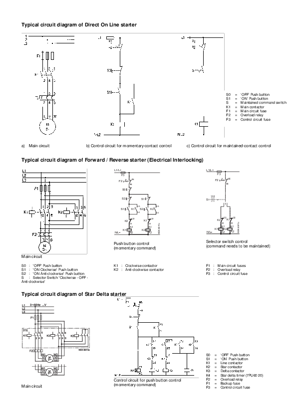
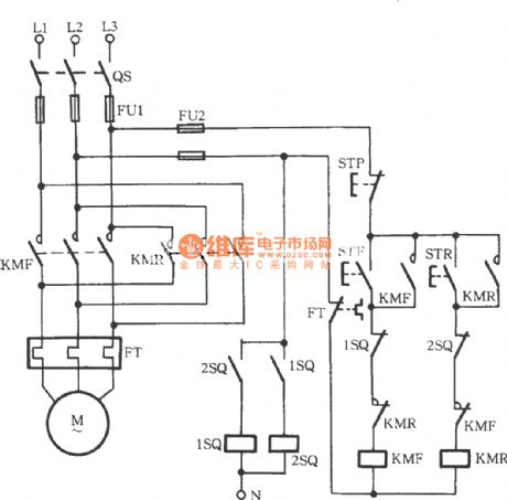
Figure 5 forwardreverse motor wiring diagram. I shown the complete method.

Control Circuit For Forward And Reverse Motor
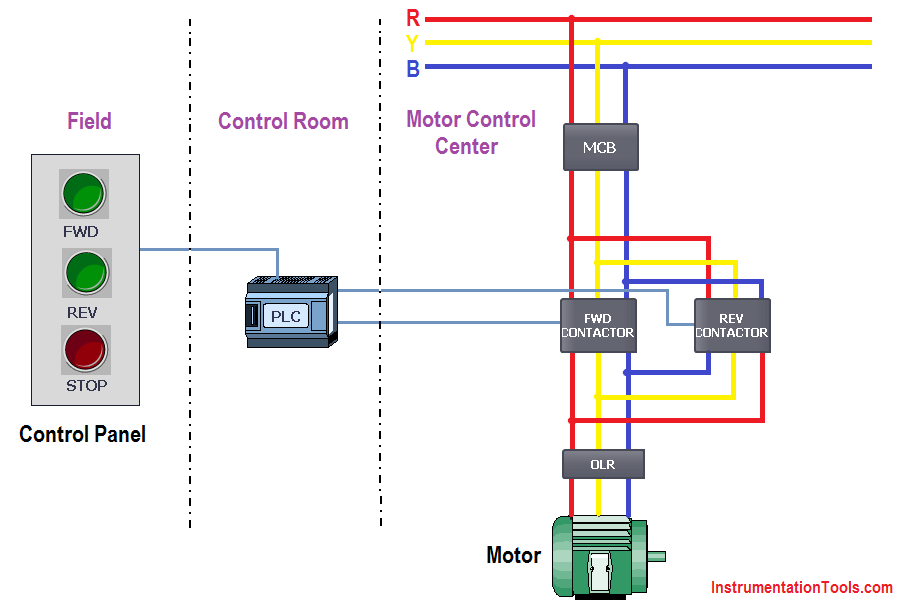
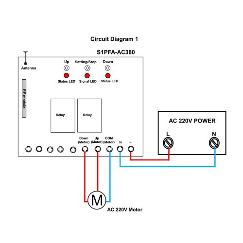
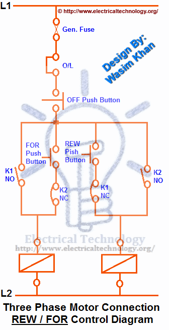
Reverse forward control diagram. A schematic diagram of a forward reverse control for a single phase split phase motor is shown in figure 2913. Within the above 3 phase motor forward reverse schematic. Forward reverse motor control diagram for three phase motor for three phase motor forward reverse control circuit. This suggests that the contactors also required the neutral wire. Reverse forward motor control circuit diagram for three phase motor. Here i showed the forward reverse wiring diagram.
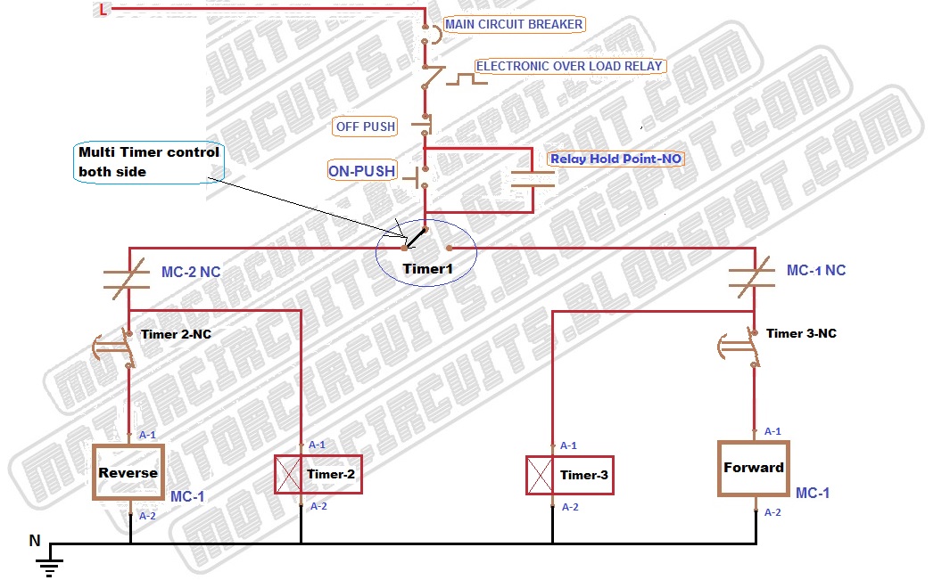
Notice that the control section is the same as that used for reversing three phase motors. Here i had shown that the both cont actors are 220 vac. As the name defines forward reverse starter is used to run the motor in both sides forward and reverse. How to read an electrical diagram lesson 1 duration. Here first i am sharing with the main wiring diagram. Three phase motor connection stardelta y δ reverse and forward with timer power control diagram as we have already shared the starting method of three phase motor by star delta starter with timer circuit power and control circuits.
In the event of an overload both motor starter output. The three phase incoming supply molded case circuit breaker mccb two magnetic contactors. Control circuit for forward and reverse motor checkout video on 4 way switch wiring. In the below main wiring diagram. A wiring diagram is a simplified conventional pictorial representation of an electrical circuit. In this article we are going to learn about the forward reverse starter.
The overload contacts are connected to l1 on one side and to the plcs input module on the other input 003. It reveals the components of the circuit as simplified forms as well as the power as well as signal links in between the tools. Forward reverse control diagram now come to the controlling wiring. In the diagram i connect the incoming three phase supply l1 l2 l3 to the mccb circuit breaker molded case circuit breaker. Forward reverse starter diagram. In this wiring diagram both the forward and reverse coils have their returns connected to l2 and not to the overload contacts.
Related queries forward reverse motor wiring reverse forward motor control circuit diagram reverse forward motor connection reverse forward motor control circuit diagram with limit switch reverse. The figure given below shows the control and power diagram of forward and reverse starter diagram. In this example run winding lead t1 will always be connected to l1 and t4 will always be connected to l2. I convert the diagram in two parts for better understanding. Variety of single phase motor wiring diagram forward reverse. We use 2 magnetic contactors as forward reverse switch.
Now in the below diagrams three phase motor will rotate in two directions viz forward and reverse. The neutral wire first goes to the thermal overload relay nc contacts and to the sunshine indicator.


