The electromagnet that holds the starter in the run position is in the field circuit. Induction motors started with direct on line dol starter.
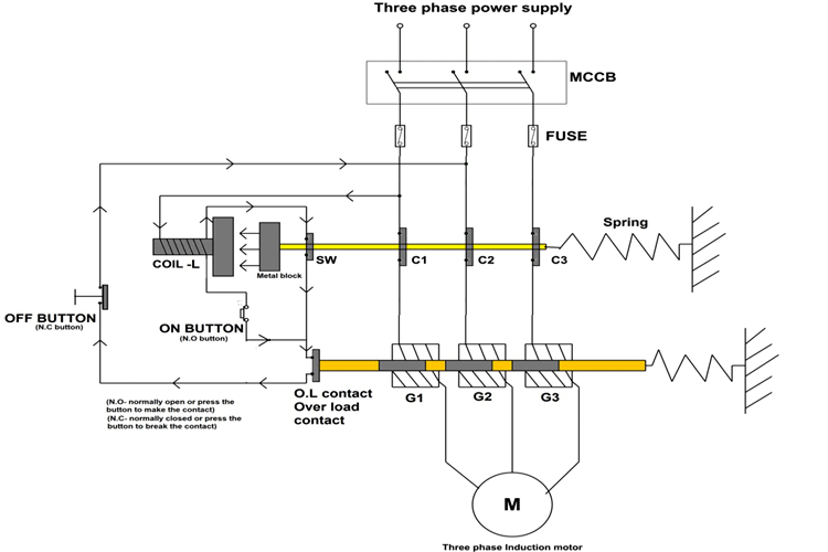
Construction And Operation Of Direct Online Starter Circuit
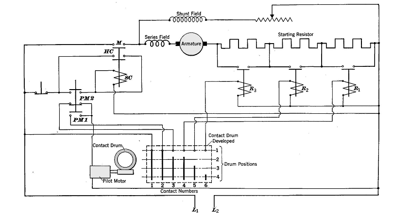
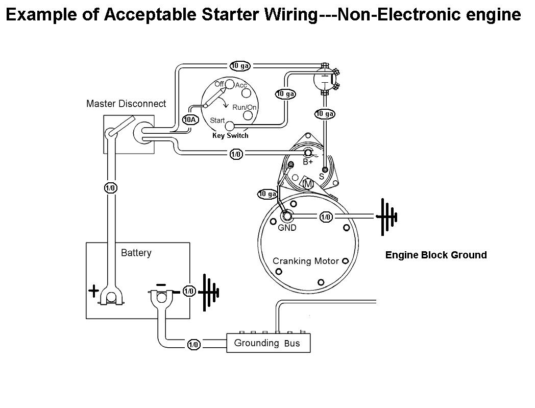
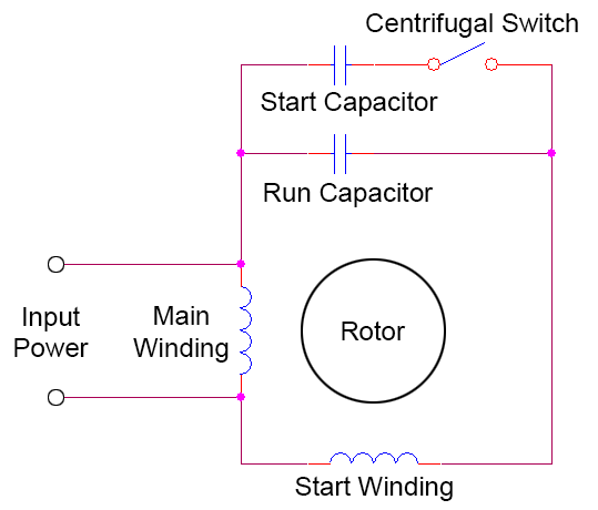
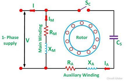
Circuit diagram of starter motor. Your motor starter may use wiring which is internal to the starter wiring which is different than the diagrams etc. A wiring diagram is a streamlined standard pictorial representation of an electric circuit. When the stator windings of an induction motor are connected directly to its 3 phase supply a very large current 5 7 times full load current flows initially. This surge current reduces as the motor accelerates up to its running speed. Assortment of motor starter wiring diagram pdf. Wiring diagram will come with numerous easy to stick to wiring diagram instructions.
It shows the elements of the circuit as streamlined shapes and the power and signal links in between the tools. Eaton motor starter wiring diagram whats wiring diagram. Star delta starter motor control with circuit diagram in hindi starter motor wiring diagram. Star delta y δ 3 phase motor starting method by automatic star delta starter with timer. It reveals the parts of the circuit as simplified shapes and the power and signal links between the gadgets. Ignition switch starter solenoid starter relay.
The arm is spring loaded and is rotated in the clockwise direction gradually reducing the armature resistance as the motor accelerates. It really is supposed to help all of the average consumer in creating a correct method. A wiring diagram is a simplified traditional photographic representation of an electric circuit. If you are not sure of how to make the connections on your equipment hire an electrician. Collection of single phase motor starter wiring diagram. Three phase motor connection stardelta without timer power control diagrams.
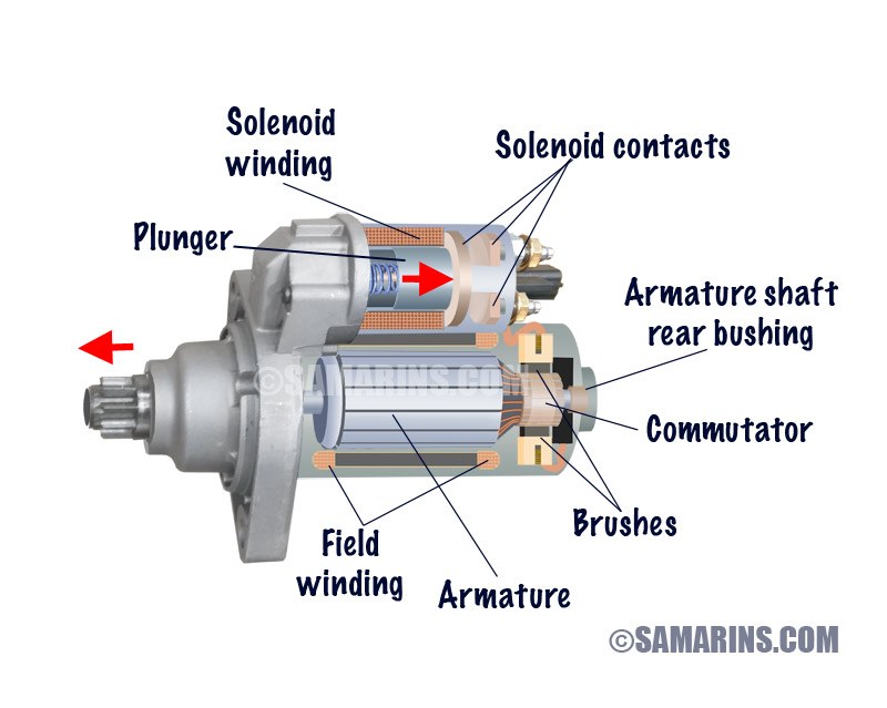
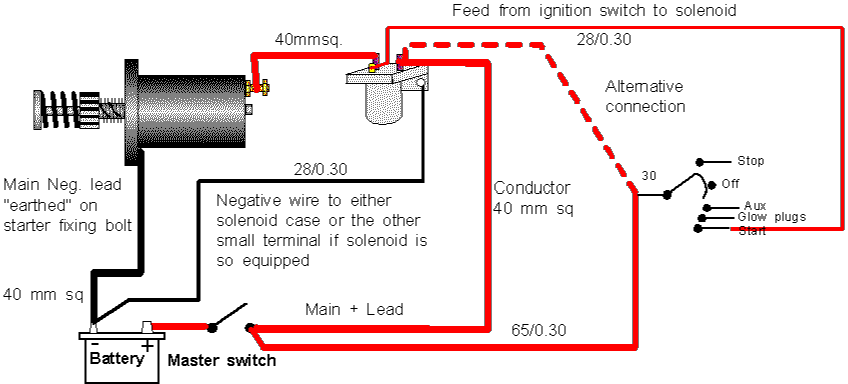
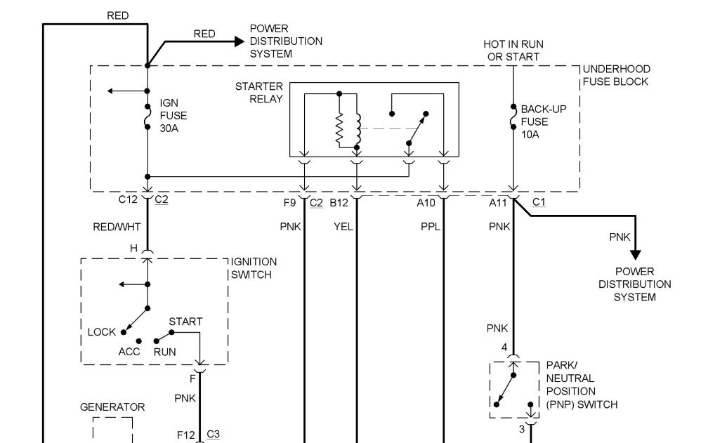
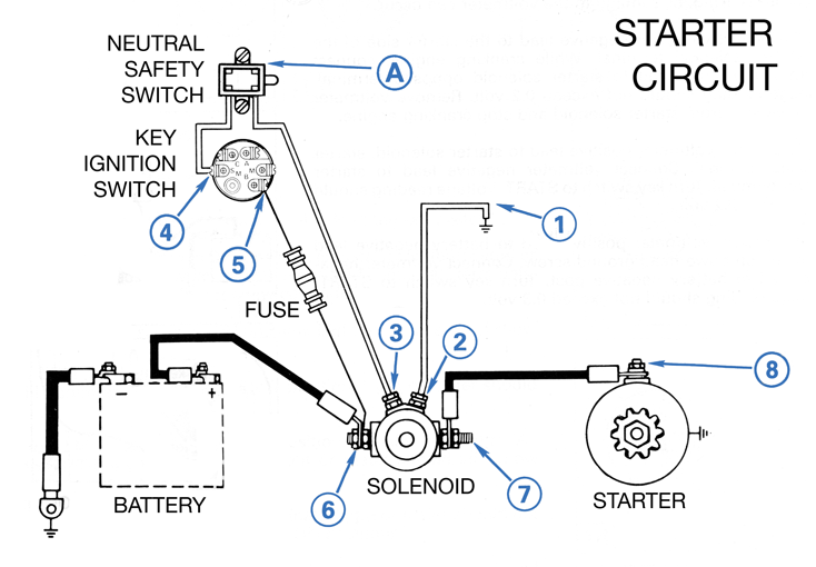
The main function of car starting circuit is using the small current from the car battery to control the large current of the car starting circuit thus to start the starter motor and power the engine. A typical starter solenoid has one small connector for the starter control wire the white connector in the photo and two large terminals. One for the positive battery cable and the other for the thick wire that powers the starter motor itself see the diagram below. These guidelines will probably be easy to comprehend and apply. Three phase motor connection schematic power and control wiring installation diagrams. Figure 2 shows a manual starter circuit diagram.
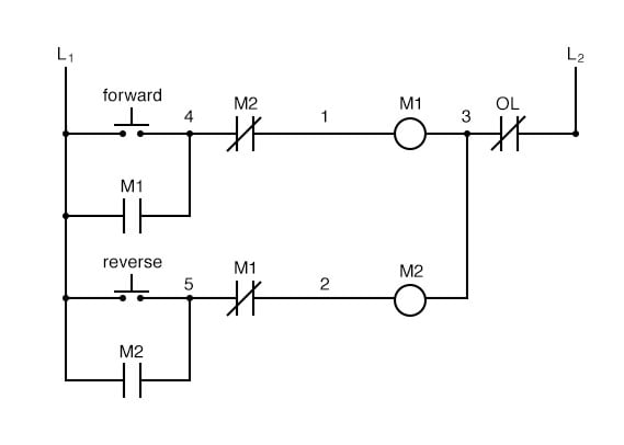
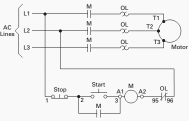
This starter is a so called three point starter. There are three main components in the switch starting circuit. Please refer to the manufacturers literature if in doubt. A wiring diagram is a kind of schematic which utilizes abstract photographic symbols to show all the interconnections of parts in a system. All diagrams are intended to illustrate the logic of a latching contol circuit.
