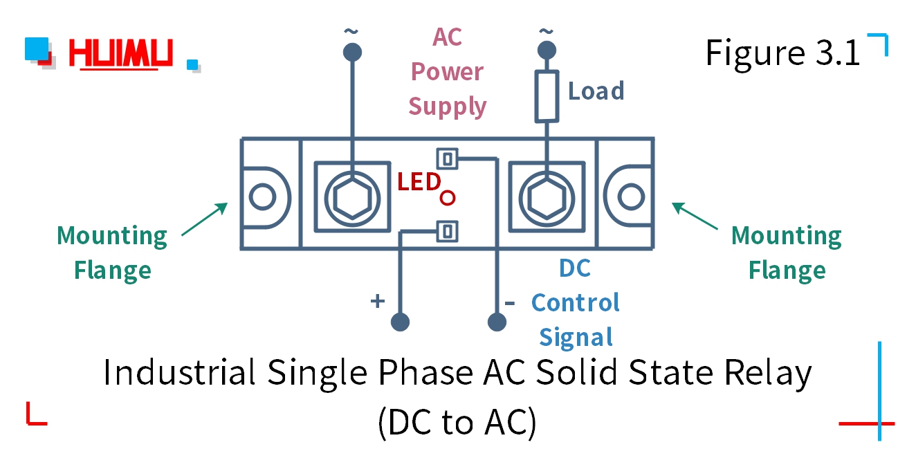
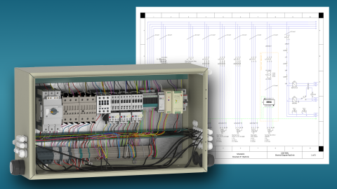
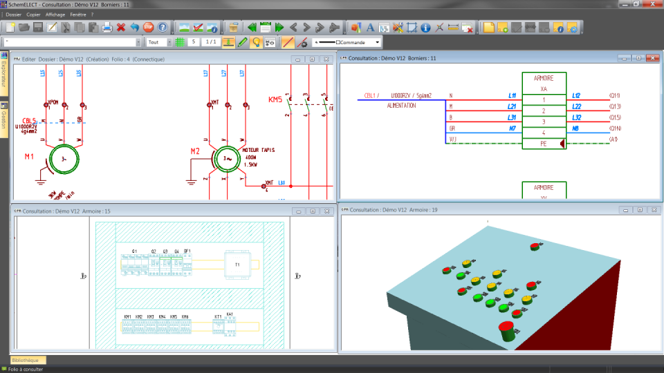
Wiring diagram software with built in stencils for fast and efficient electrical wiring diagram design. Assortment of baldor reliance industrial motor wiring diagram.

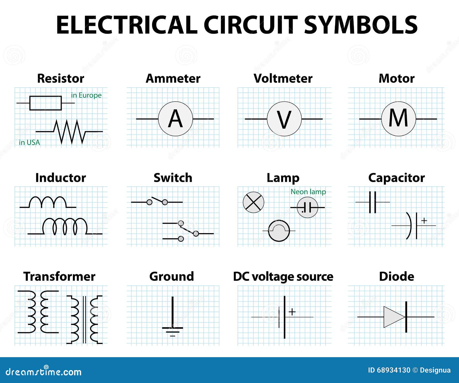
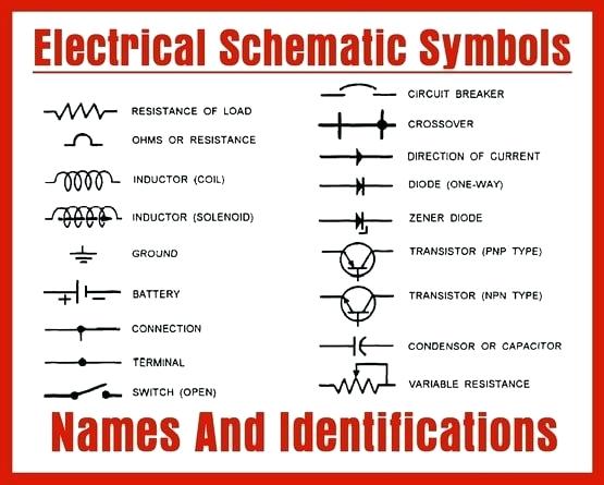
Wiring Schematic Symbols Chart Car 16 Brillenstudio Weichert De
Industrial wiring circuit diagram. You may also read. The wiring diagram for connecting thee phase motor to the supply along with control wiring is shown in figure below. The three phases are then connected to a power interrupter. One line diagram of simple contactor circuit. Variety of industrial control transformer wiring diagram. The contactor contains large load contacts that are intend to handle large amount of current.
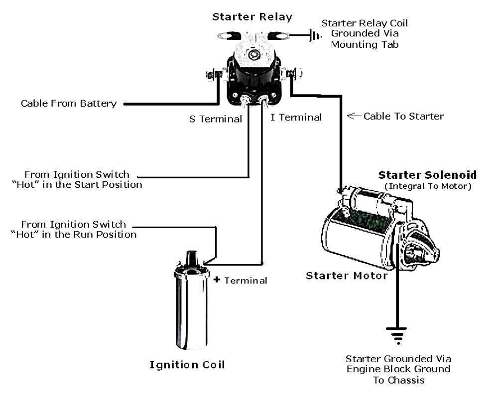
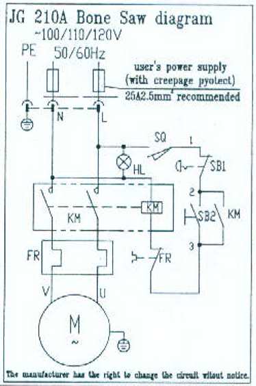
An example of a wiring diagram for a motor controller is shown in figure 1. Feb 5 2020 explore elects agass board electrical diagram on pinterest. Electrician circuit drawings and wiring diagrams youth explore trades skills 3 pictorial diagram. A diagram that uses lines to represent the wires and symbols to represent components. Dashed lines indicate a single purchased component. The components of the diagram will include a transformer low voltage source thermostat switch humidistat switch low voltage damper actuator load low voltage light load and a contactor with a low voltage coil load.
It reveals the components of the circuit as simplified forms and also the power and also signal connections between the tools. A wiring diagram is a simplified standard pictorial depiction of an electrical circuit. Easy to create wiring plans schematics circuit diagrams and more. This is a start stop push button control schematic which includes contactor m overload relay control transformer and push buttons. A wiring diagram is a streamlined traditional photographic depiction of an electric circuit. This system uses 3 phase ac power l1 l2 and l3 connected to the terminals.
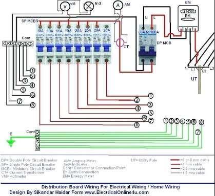
A diagram that represents the elements of a system using abstract graphic drawings or realistic pictures. See more ideas about electrical diagram electrical circuit diagram electrical engineering. Usually the wiring diagram refers to the electrical schematic or circuits diagram. Three phase electrical wiring installation in home iec nec. Generic nomenclature will suffice since we are demonstrating the making of a wiring diagram. Note that symbols are discussed in detail later.
How to connect a portable generator to home supply system three methods a simple circuit diagram of contactor with three phase motor.
