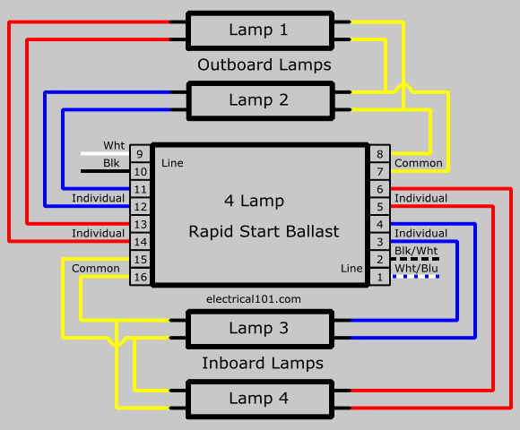
It shows the components of the circuit as simplified shapes and the talent and signal connections together with the devices. 06102018 06102018 6 comments on osram quicktronic ballast wiring diagram.

Wiring Diagram For Osram Quicktronic Ballast
Osram quicktronic ballast wiring diagram. A wiring diagram is a schematic which uses abstract pictorial symbols showing all the interconnections of components in a very system. Osram quicktronic high efficiency qhe. Up to 6 in energy savings compared to standard t8 low power electronic ballasts without compromising light output maximum energy savings when compared to f40t12 magnetically ballasted systems 2. It reveals the components of the circuit as streamlined shapes as well as the power as well as signal links between the gadgets. Sylvania quicktronic ballast wiring diagram whats wiring diagram. 182 cross reference guide disclaimer.
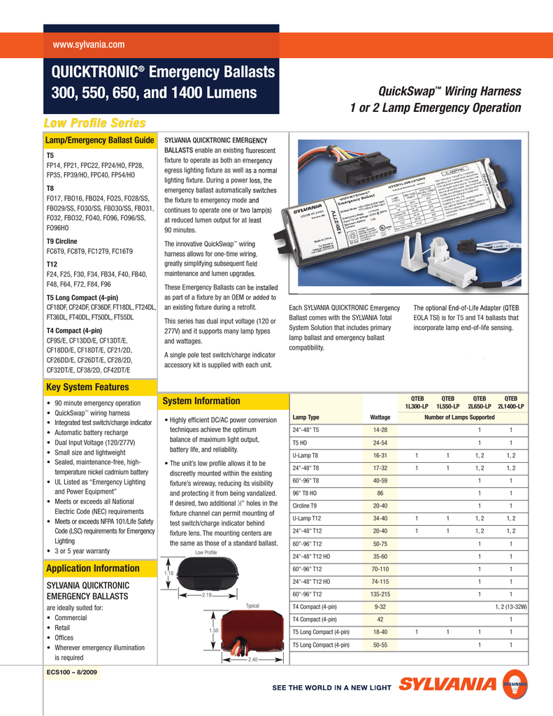
Same light less power. This cross reference guide is intended as an aid for identifying comparable products as a convenience to the user. Osram quicktronic ballast wiring diagram. Quicktronic high efficiency qhe energy saving electronic t8 ballasts offer several advantages. Couple quicktronic high efficiency fluorescent ballasts with high efficacy long life octron t8 and pentron t5 and tho lamps. Number osram sylvania advance formerly magnetek ge howard quickcross the smart electronics in sylvania quicktronic ballasts allow them to outperform the competition.
Collection of sylvania quicktronic ballast wiring diagram. Keeps remaining lamps lit if one or more go out. Quicktronic 32 isn sc unv electronic ballasts have very low harmonic distortion 10 thd for high system performance. Osram sylvania does not. Operate octron t8 lamps with maximum efficacy and high lumen output over 30 energy savings when compared to f96t12 magnetically ballasted systems. Wiring diagrams are made up of a pair of things.
Quicktronic high efficiency electronic ballasts. Program start electronic t8 ballasts offer several advantages. Osram quicktronic ballast wiring diagram wiring diagram is a simplified all right pictorial representation of an electrical circuit. 21 block diagrams of a digitalanalog dimmable ecgs 06 211 block diagram of a digital dimmable ecg with dali interface 06 212 block diagram of an analog dimmable ecg with 110 v interface 06 22 dali in comparison to 110 v and knxlon 07 221 dali and 110 v properties 07 23 installation and wiring instructions for dimmable. Symbols that represent the constituents within the circuit and lines that represent the. A wiring diagram is a simplified standard pictorial representation of an electric circuit.
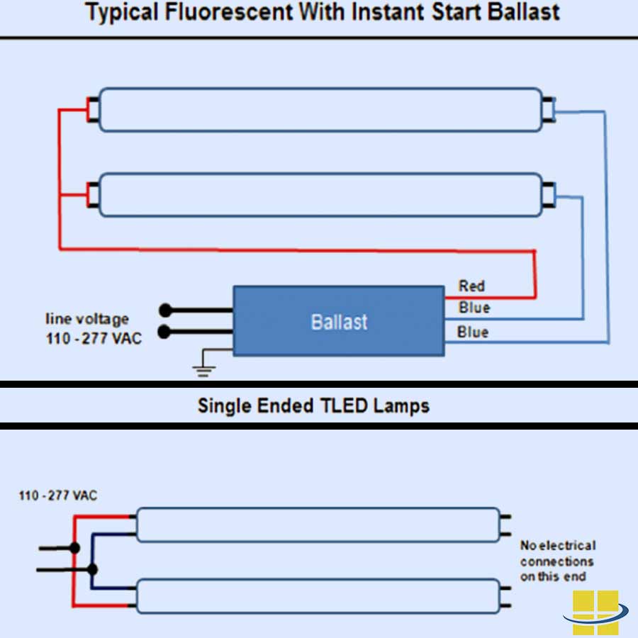
Instant start also provides for maximum remote wiring distances. Controllable ballasts for powerline 0 10v bi level or dali dimming. Quicktronic system 59 isn unv electronic t8 ballasts offer several advantages. Quicktronic 32 isn sc unv uses instant start operation to provide the highest system efficacy and to assure low temperature starting capability.


