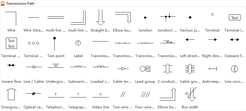
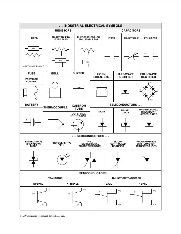
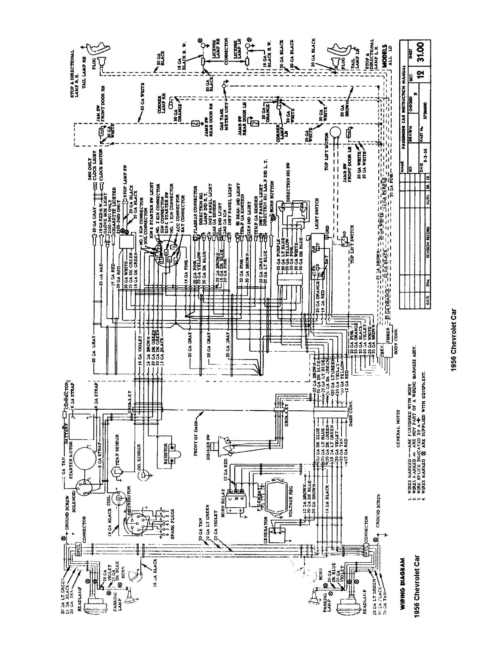
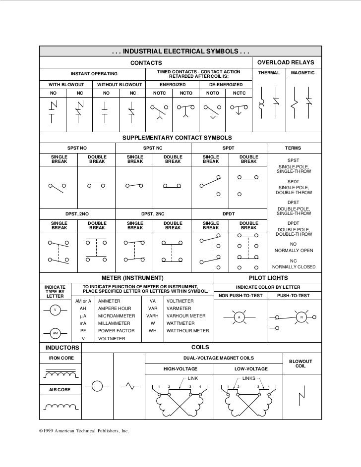
Here is a standard wiring symbol legend showing a detailed documentation of common symbols that are used in wiring diagrams home wiring plans and electrical wiring blueprints. Basics 10 480 v pump schematic.

Industrial Compressors 3 Phase Wiring Diagram Gedownload
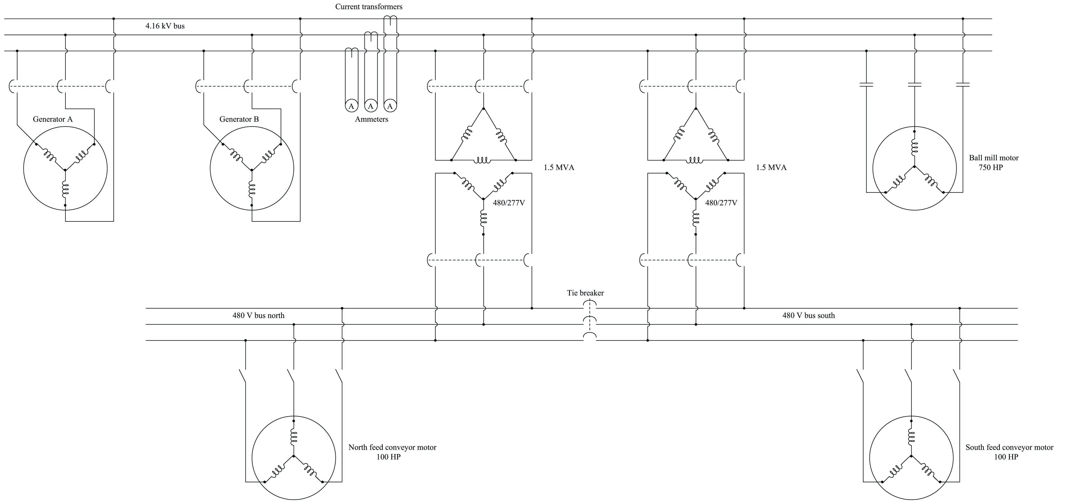
Industrial electrical diagram. Electrical and electronics diagrams usas y1415 1966 usa standard approved includes the following. All you need is a powerful software. Basics 8 aov elementary block diagram. Here are 5 free electrical diagram software for windowsthese software help you design an electrical circuit diagram by adding different devices and electrical instruments. Plumbing and piping plan. The one line diagram is similar to a block diagram except that electrical elements such as switches circuit breakers transformers and capacitors are shown by standardized schematic symbols.
Recognizing electrical schematic symbols here are some of the standard and baisc symbols for various components for electrical schematics. Parts and assembly drawing. Basics 13 valve limit switch legend. A one line diagram or single line diagram is a simplified notation for representing an electrical system. The diagram also shows numbering for the wires in the device. Wiring diagrams use simplified symbols to represent switches lights outlets etc.
Basics 11 mov schematic with block included basics 12 12 208 vac panel diagram. It wasnt so easy to create electrical symbols and electrical diagram as it is now with electrical diagram symbols offered by the libraries of electrical engineering solution from the industrial engineering area at the conceptdraw solution park. This solution provides 26 libraries which contain 926. To read electrical schematics the fundamental electrical schematic symbols should be understood. Then well talk about how those symbols are connected on the schematics. For example lets say our thermostat is a t87f our humidistat a w43a 14 the damper motor an m836 the contactor or relay an r8222d the light a 32rg18 2111t and an at140a1000 transformer.
Basics 14 aov schematic with block included. Basics 9 416 kv pump schematic. How to create electrical diagram. Basics 6 72 kv 3 line diagram. These numbering schemes are often particular to each facility but there are tools to help make wire labels that will appear in the final controls cabinet. Basics 7 416 kv 3 line diagram.
This is essential for industrial control systems that may contain hundreds or thousands of wires. 15 1 scope 15 2 definitions 15 3 general infonnation 15 4 single line diagrams general 15 5 single line diagrams electronics and communications 15 6 single line diagrams power switchgear and industrial control. Piping and instrumentation design. You can use these software for making the electrical design of buildings or design of a specific electrical circuit. To label the diagram now you will have to know what devices youre using and how they work.
