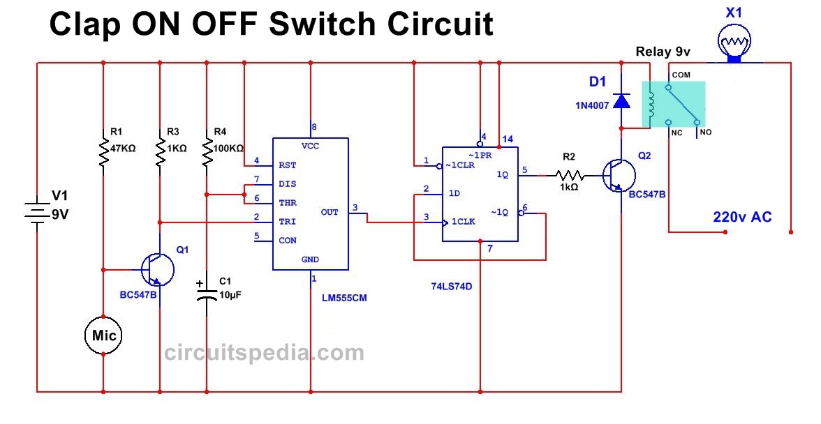
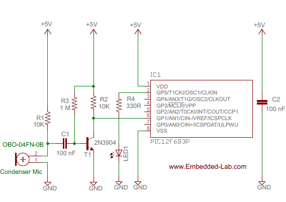
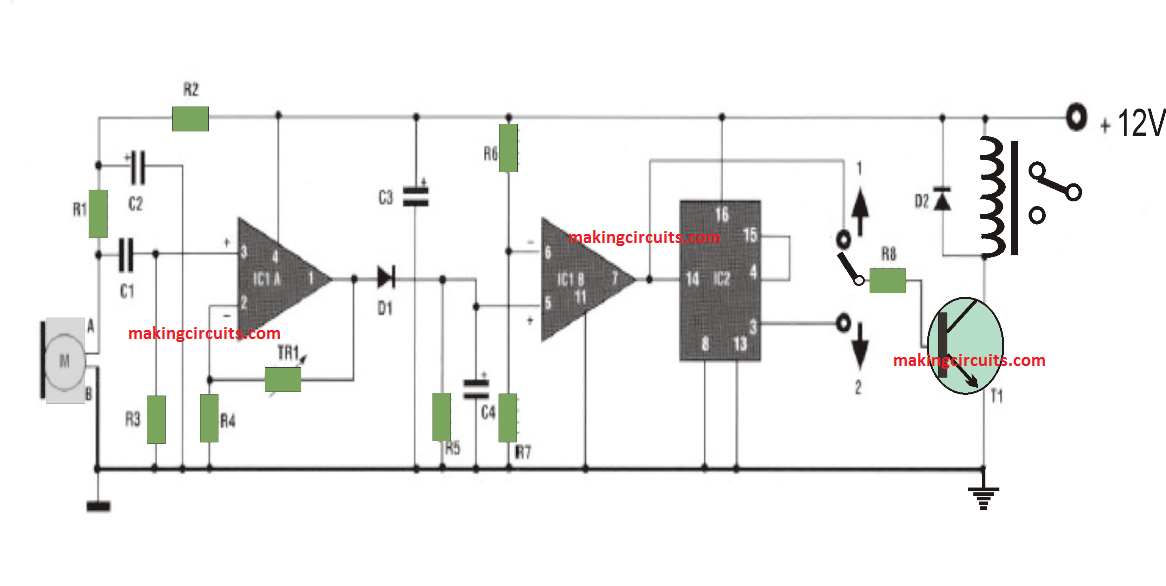
A resistor with value between 220 ohm and 470 ohm is used in series with the led r3 in the circuit diagram. If you want to design a switch circuit to turn on and turn off without reach a physical switch then try this simple clap switch circuit with relay this circuit is designed with timer ic 555 dual d flip flop ic 7474 and a electromagnetic relay.
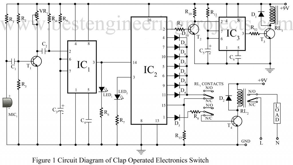
Clap Switch Circuit Using 555 Engineering Projects
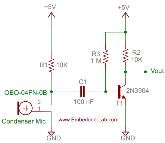
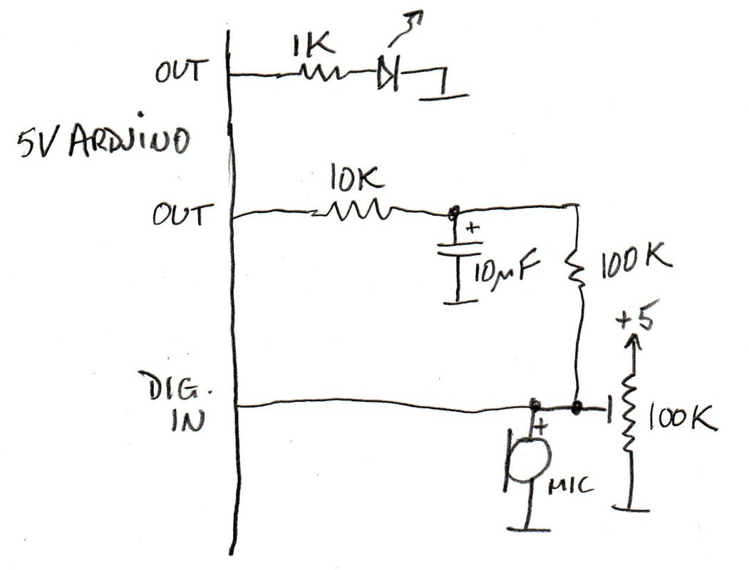
Clap switch diagram. How to make sound clap switch lights on off control light fan with clap using cd4017 ic duration. The negative or gnd pin of the electret microphone is the pin that connects to the body of the microphone. Multi electric 161466 views. Although its name is clap switch but it can be turned on by any sound of approximately same pitch of clap soundthe main component of this clap switch circuit is the electric condenser mic which has been used as a sound sensorcondenser mic basically converts sound energy into electrical energy. Similarly when 555 timer generates. This is another clap on off circuit diagram using 555 timer and 7474 icwhen clap the load is switch on and when again clapped then load is switch off.
It gets back to its original state when an external clock pulse is given to a monostable oscillator. Clap switch breadboard layout and circuit diagram. This construction will give mono pulse when trigger received from mic the duration of pulse time varies respect to r2 and c2 connected with ic555. When you clap for the second time the relay is deactivated and the light is turned off. The entire function of the clap switch is based on cd 4017 ic and ne 555 ic. Build the circuit as shown in the breadboard layout and circuit diagram below.
Clap switch circuit using 555 and 4017. Clap switch circuit diagram. Clap switch working consider the above circuit into 2 parts the job of the left part of this circuit is to give the low signal to the right part which has 555 timer. Share on tumblr this clap switch circuit using ic 555 is a hobby circuit makes led to glow while you clap or make louder noise. Circuit is work by the detection of clap sound. We already seen the right part of the circuit in how to get the monostable output using 555 timer.
When you clap once the relay is activated and the light or any load is turned on. This clap operated on off switch circuit is useful to on off any appliance. Ic 555 is a timer ic. It is similar to an oscillator like monostable which has only one stable state. Clap switch is an interesting hobby circuit which turns on the lights with a clap sound. You can use this circuit concept in many ways to activate sound based project.
In the first circuit i will control a single relay using clap switch. This is simple clap switch circuit diagram.


