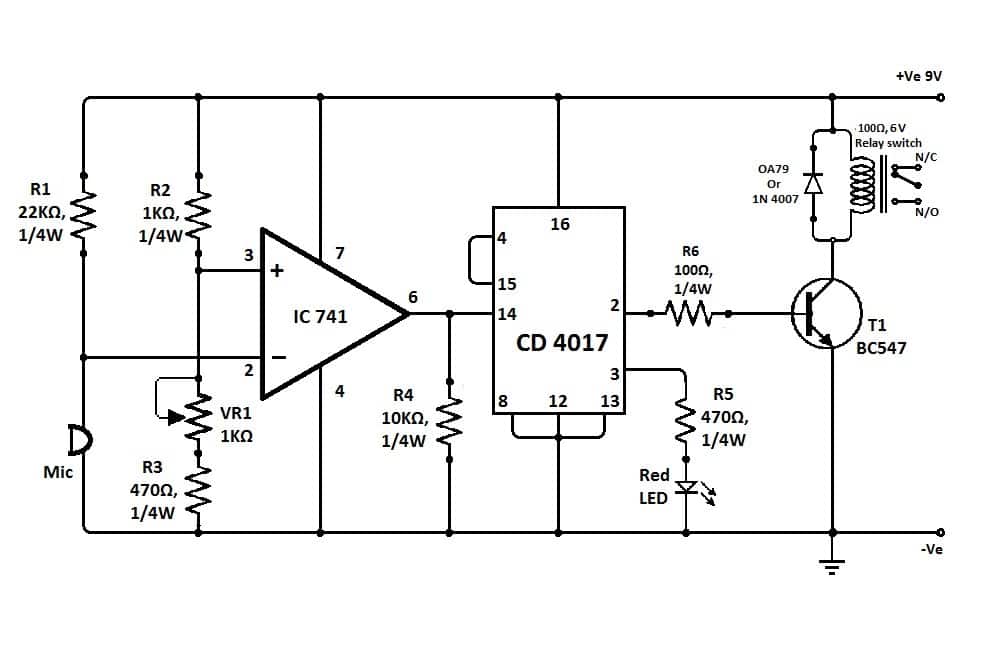
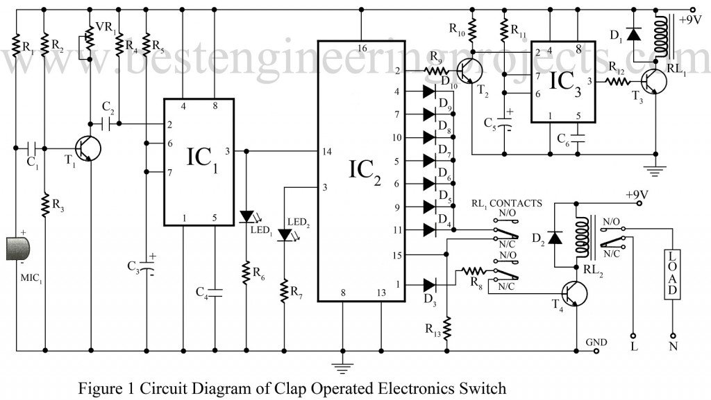
This is the circuit of a very sensitive clap switch. When you clap for the second time the relay is deactivated and the light is turned off.

To 4958 Clap Switch Circuit Diagram Schematic
Clap switch circuit diagram using ic 4017. The output state of the switching device circuit can only change when the circuit receives two claps within a time period that will be determined by the rc component value in the circuit. Cd 4017 ic ic2. Circuit description today we are going to make a simple clap switch circuitthis is a simple clap switch circuit with high sensitivity. It switches onoff a white led or electrical. A relay is a switching device which is used to switch the circuit on when required and turn off whenever required. Although its name is clap switch but it can be turned on by any sound of about same pitch of clap sound.
I have made this circuit as simple as possible you can find many complex clap switches using 555 ic with some more components in it and merely doing the same thing. Solar disc light diy. Shayad apke circuit diagram me ic2 me 16. It works as a switch which makes devices on and off by making a clap sound. Although its name is clap switch but it can be turned on by any sound of approximately same pitch of clap soundthe main component of this clap switch circuit is the electric condenser mic which has been used as a sound sensorcondenser mic basically converts sound energy into electrical energy. The main component of the circuit is the electric condenser mic which has been used as a sound sensor.
The transducer microphone is connected to an amplifier sub circuit which is connected to timer ics 3. It switches onoff a white led or electrical appliances through claps. Friends in this video i will show you how to make a clap switch circuitsimple clap onoff switch using 4017 iccontrol light fan by clapfriends it is a very simple circuit and you can easily. The circuit can sense the sound of claps from a distance of 1 3 meters. Really great stuff on 4017 ic. It switches onoff electrical appliances through clapsin the circuit i will control a single relay using clap switch.
A resistor is an electronic component which opposes the flow of current or prevents. When you clap once the relay is activated and the light or any load is turned on. Sensitive clap switch circuit d mohankumar 04242010. Resistors 100 ω r1 560 ω r2 46 kω r3 18 kω 3 r4 33 kω r5. Clap on off switch with 4017 ic and bc547 transistor. Ic 4017 circuits and projects for hobby electronist and school.
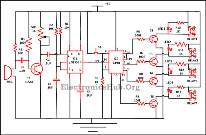
Clap switch circuit using 555 and 4017. The main components of the circuit are. This is the circuit of a very sensitive clap switch. Condenser mic picks up sound vibrations c by the clap. 555 ic ic 1. In the first circuit i will control a single relay using clap switch.
Clap switch is an interesting hobby circuit which turns on the lights with a clap sound. Simple clap switch using ic 741 and 4017. Condenser mic basically converts sound energy into. Even make things simpler.


