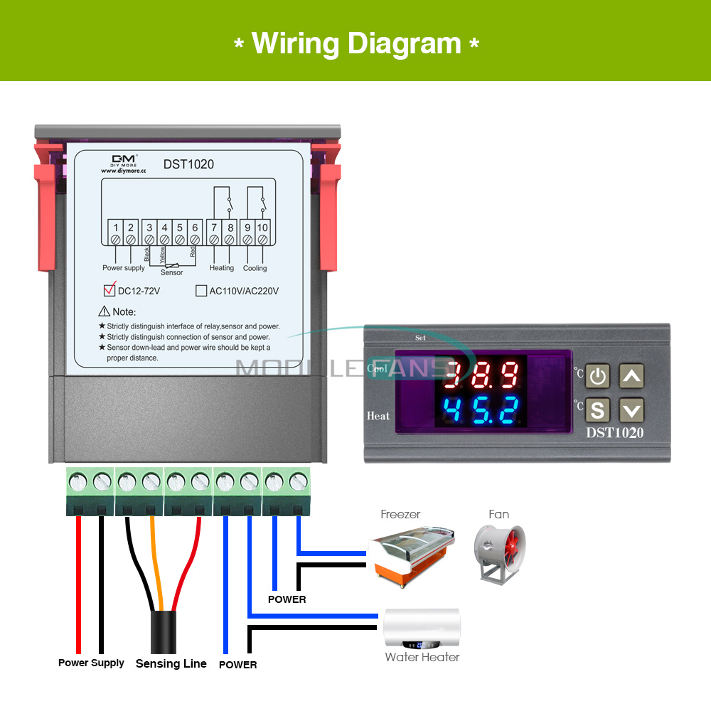
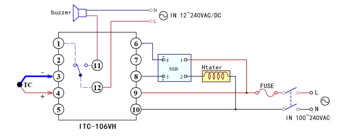
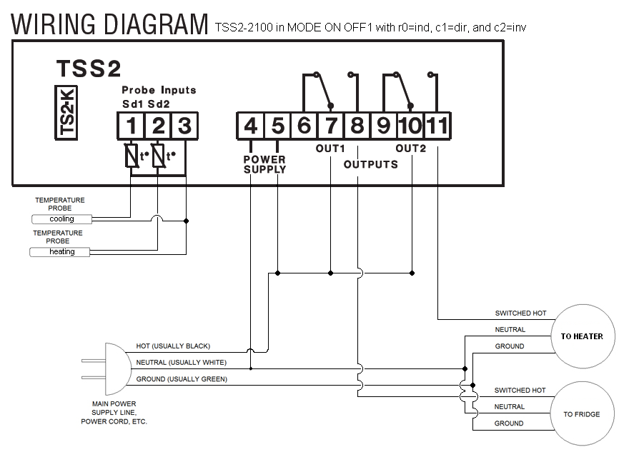
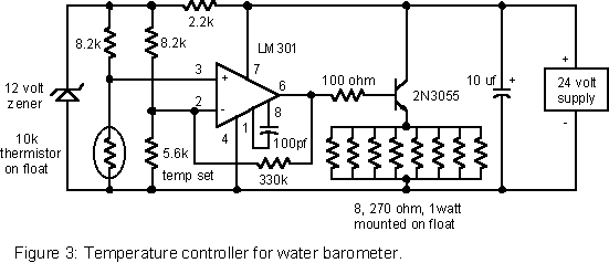
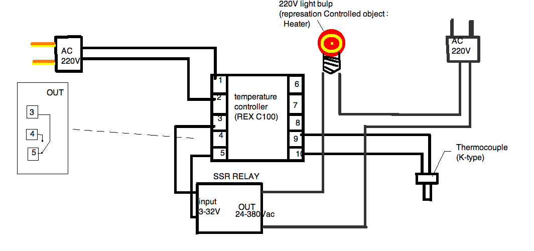
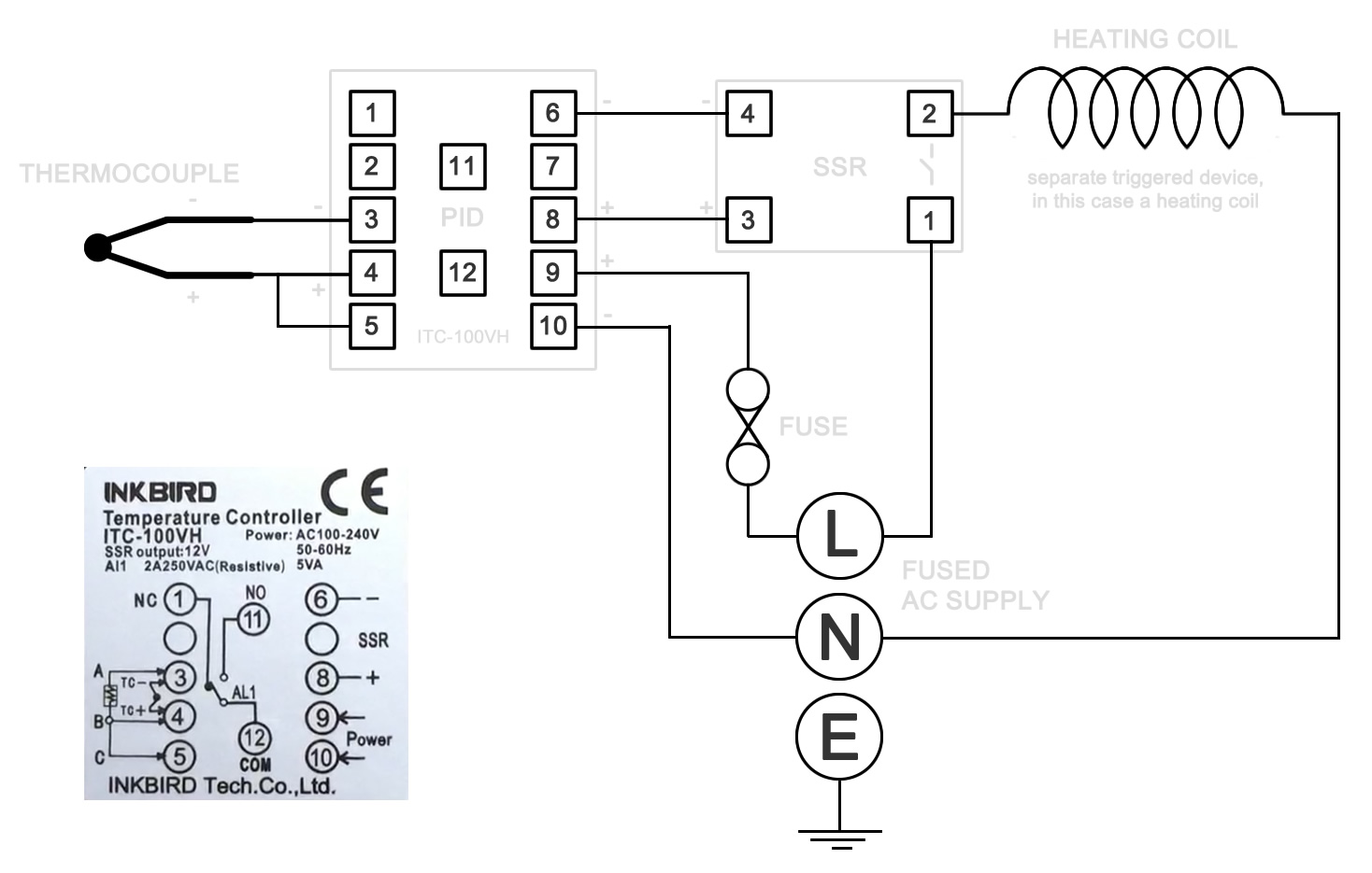
2 shows circuit diagram of the digital temperature controller. To accurately control process temperature without extensive operator involvement a temperature control system relies upon a controller which accepts a temperature sensor such as a thermocouple.
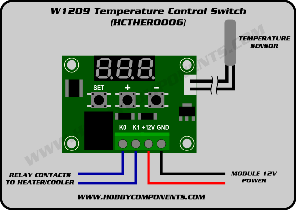
W1209 Temperature Control Switch Hcther0006 Forum
Temperature controller connection diagram. Pid temperature controller in a box duration. Pin 20 to 23 of port 2 of microcontroller are connected to transistors bc547 of port 2 of microcontroller is connected to transistors bc547. A connection diagram is displayed on the side of each controller. Ause of mov across supply of temperature controller snubber circuits across loads are recommended buse s connection diagram. A wiring diagram is a streamlined traditional pictorial representation of an electric circuit. The controller has been designed and fabricated using the op amp ic 741 and a 1k thermistor as the temperature sensor.
Pin 24 is connected to another transistor bc547 which drives the relay. The circuit is built around microcontroller pic16f877a ic1 precision thermocouple amplifier ad8495 ic2 k type thermocouple connected at con3 162 lcd lcd1 single changeover relay rl1 and a few common components. Circuit diagram temperature control. Temperature controller connection with solid state relay duration. The voltage across the thermistor ie. Collection of ranco temperature controller wiring diagram.
Most connections and numbers are identical however. It reveals the parts of the circuit as streamlined forms and also the power and signal links in between the tools. The ratio arms r1 and r2 of the bridge are kept fixed say unity. A wiring diagram is a simplified conventional pictorial representation of an electrical circuit. Connect rtd1 rtd2 of a b rtd 6 7 8 910. Pin 00 to 06 of port 0 of microcontroller is connected to 7 segment display.
It shows the parts of the circuit as streamlined forms as well as the power and also signal connections in between the devices. 1 for thermocouple tctc 6 7 8 910 thermocouple 1 for two wire pt 100. It is based on the principle of wheatstone bridge. 7hup 7huplqdo v 1 2 are the control output for heating cooling unit. Sn technical 37706 views. Assortment of ranco temperature controller wiring diagram.
Connect pt100 between terminal no. 7 8 2 for three wire pt 100. See figure 1 the picture below is an example the type you purchased may deviate from this. The temperature controller takes an input from a temperature sensor and has an output that is connected to a control element such as a heater or fan. Digital temperature controller schematic diagram. Short terminals 8 9.
A proportionalintegralderivative controller pid controller or three term controller is a control loop feedback mechanism controller widely used in indu.


