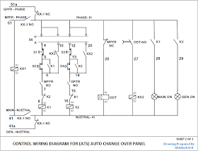
When the switch s1 is at position 1 reset pin of the 555 timer is grounded. This contact being in series with the coil of the other contactor will not allow the other contactor to close.
Manual Amp Auto Ups Inverter Wiring Diagram With Changeover
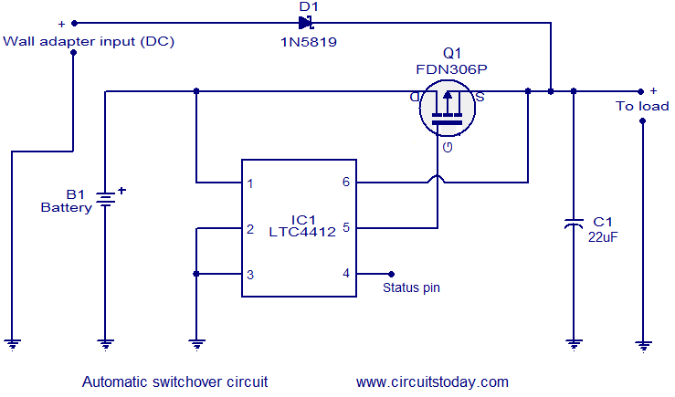
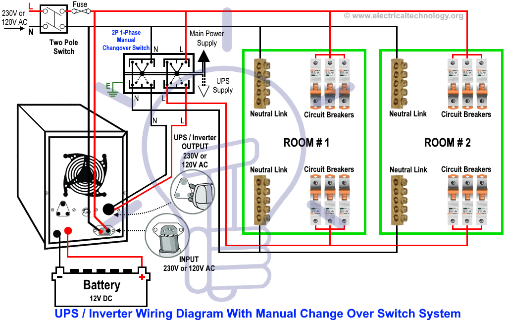
Change over switch circuit diagram. A contactor when closed opens its own auxiliary contact. This circuit can be used for the automatic switchover of a load between a battery and a wall adapterltc4412 controls an external p channel mosfet to create a near ideal diode function for power switch over and load sharing. This post i will shown the complete method of manual or handle change over switch the knob type manual changeover switch wiring same like handle change over switch and its just like a voltmeter sector switch. The circuit diagram shown here is of a automatic changeover switch using ic ltc4412 from linear technologies. In this automatic changeover switch for generator circuit diagram the contactors of the generator are indicated kg and km. In our step by step electrical wiring installation tutorials series we will show how to wire and connect single phase and three phase automatic and manual changeover and transfer switches to the home distribution board to use the backup power supply such us batteries power with ups and inverters or generator power in case of emergency breakdown and power outage.
Internally this reset pin is the reset pin of the sr flip flop and hence the output of 555 timer is a low logic signal. Now what i need is to have an automatic change over box circuit where we can connect seperately the grid and inverter circuit where grid line fails it should switch to inverter circuit as rccb coming after that circuit i will get its protection even inverter is on is this idea is acceptable and if yes is there any solution for that. Automatic changeover circuit operation. Manual changeover switch are mostly use in 2 types in which one have the move able knob and 2nd one the handle changeover switch. The circuit operation commences once the switch s1 is at any of its position.
Gallery of Change Over Switch Circuit Diagram