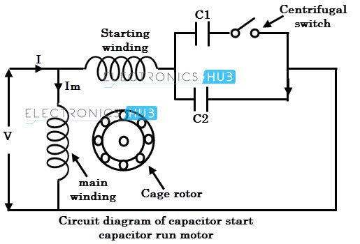
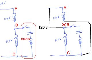
I c main winding rotor centrifugal switch v starting winding figure 50 single phase motor connection. Function of the single phase motor.

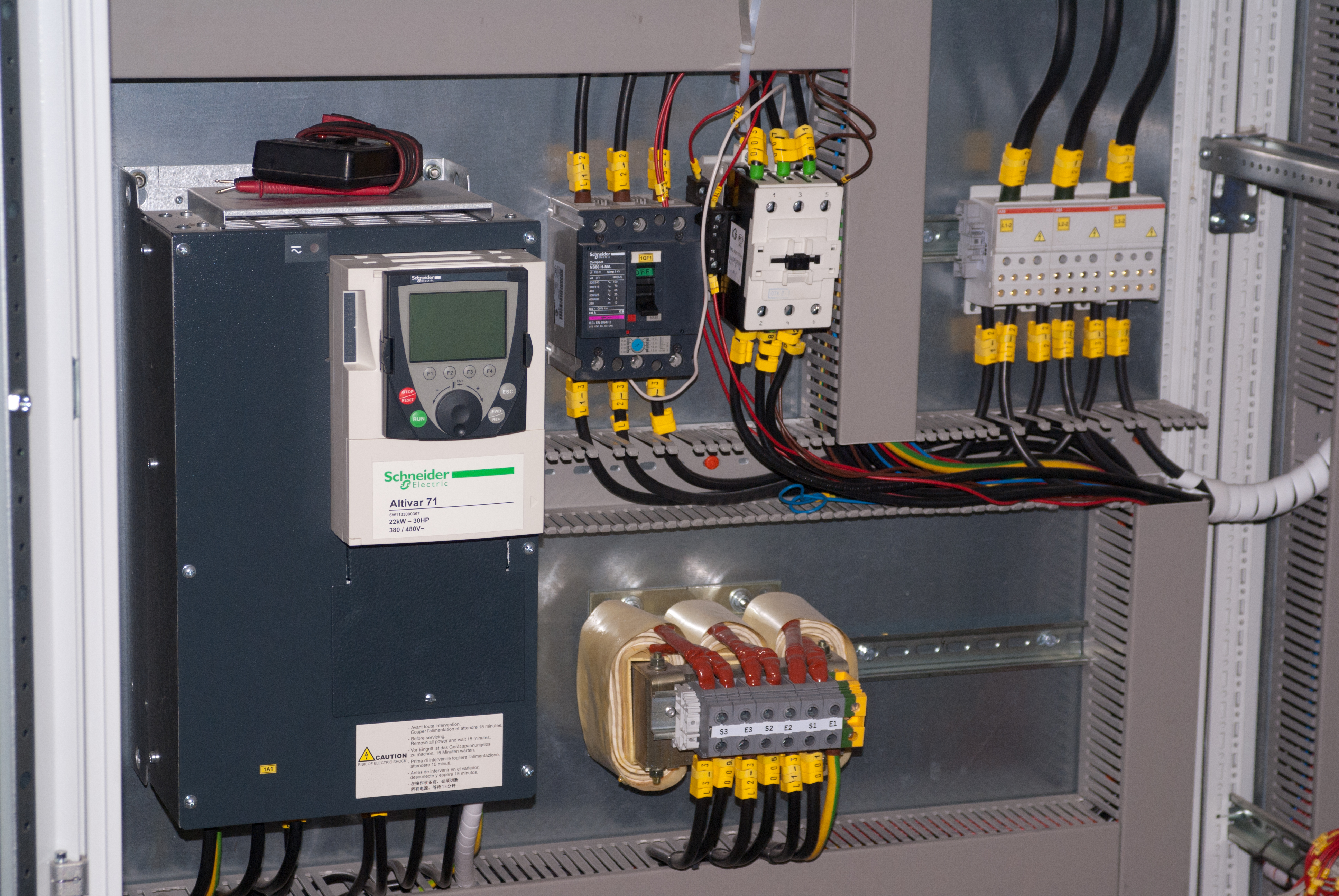
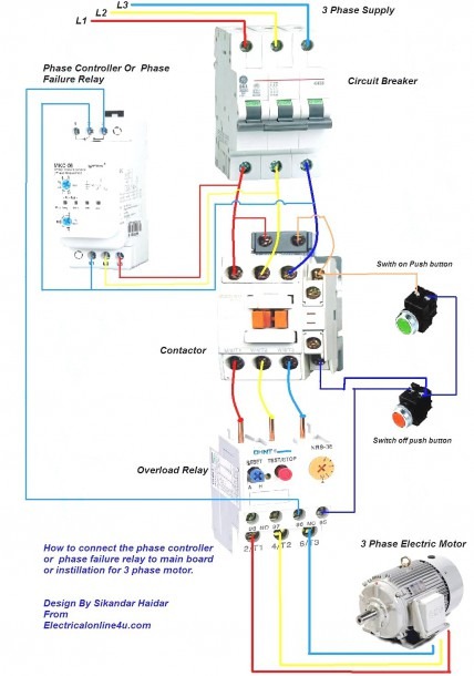
480v Motor Starter Wiring Diagram Wiring Diagrams
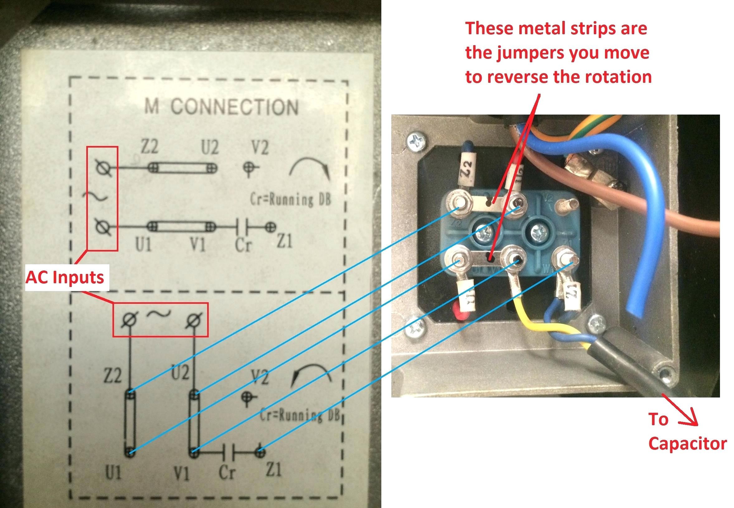
Single phase motor connection diagram pdf. Figure 17 3 shows a very basic one line diagram of the single phase motor. When the motor reaches the operating speed a centrifugal switch turns off the starting winding. Single phase motor wiring diagram forward reverse single phase motor reverse and forward connection with capacitor wiring diagram. Refrigeration and manufacturers wiring schematics also use diagrams b and c to ensure a positive troubleshoot ing application. Single phase motor wiring diagram with capacitor you will want an extensive skilled and easy to understand wiring diagram. Thermal contacts tb white m 1 z2 yellow z1 blue u2 black u1 red bridge l1 and l2 if speed controller sc is not required m 1 ln e.
A very first look at a circuit diagram could be complicated yet if you can read a metro map you can review schematics. Each component ought to be placed and linked to different parts in particular manner. Single phase motor starter wiring diagram pdf a novice s overview of circuit diagrams. Single phase induction motor figure 50 shows the connection diagram of a motor using a capacitor to generate the starting torque. Each part should be placed and connected with other parts in specific way. Frequent stopstarts andor changing of the direction of rotation will damage the motors capacitors and winding.
Wiring diagram single phase motors 1empc permanent capacitor motors 1empcc capacitor start capacitor run motors. Refer back to this diagram as the operational requirements of the single phase motor are discussed. Assortment of single phase motor wiring diagram forward reverse. Three phase motors with single phase frequency inverter should be used for frequent onoff switching. If not the arrangement will not function as it ought to be. Wiring diagram images detail.
Diagram dd5 two speed motors for all other single phase wiring diagrams refer to the manufacturers data on the motor. Diagram dd6 diagram dd7 m 1 ln e diagram dd8 ln e l1 l2 l3 sc z1 u2 z2 u1 cap. Leeson motor wiring diagram leeson 1hp motor wiring diagram leeson 3 phase motor wiring diagram leeson 5hp motor wiring diagram every electric structure is made up of various distinct components. With this sort of an illustrative guide youll be able to troubleshoot stop and complete your tasks without difficulty. The main winding of a single phase motor is designated by t1 t2 t3 and t4 and the auxiliary winding by t5 t6 t7 and t8 to distinguish it from a quarter phase motor which uses odd numbers for one phase and even numbers for the other phase b. Single phase motor wiring diagram with capacitor baldor single phase motor wiring diagram with capacitor single phase fan motor wiring diagram with capacitor single phase motor connection diagram with capacitor every electrical arrangement is made up of various unique pieces.


