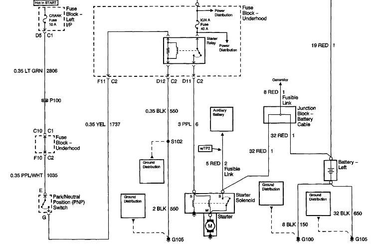
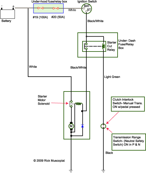
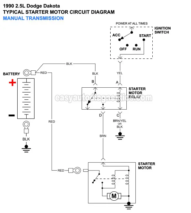
This can be helpful for the two the folks and for experts whore seeking for more information regarding how to set up a functioning atmosphere. Not every car carry the starter relay in starting system and the starter solenoid wiring diagram can be learned by with or without starter relay type.
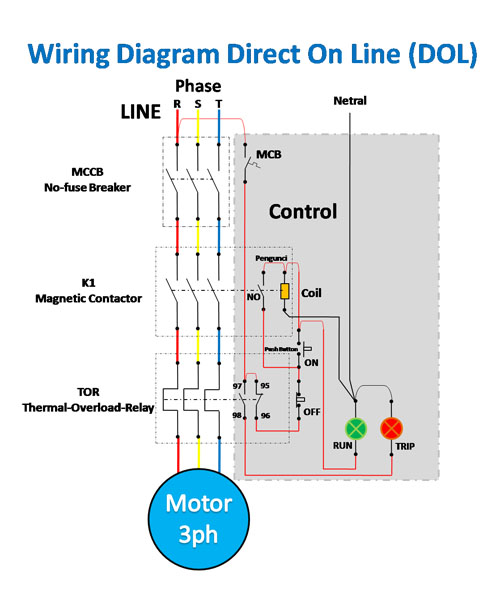
Wiring Diagram And Control Of Direct On Line 3 Phase Motor
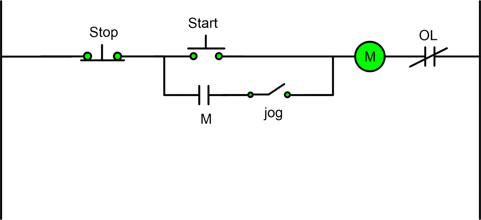
Basic starter motor wiring diagram. Starter solenoid wiring diagram. Basic wiring for motor contol circuitry of a starter two wire control two wire control circuits or low voltage release one of the common control wiring circuits used is known as two wire or low voltage release lvr. To ensure that the starter can stall automatically and the starter circuit not connected after the engine starts some cars adopt the compound relay circuit with safety driving protection. This is a picture of the basic principles of any starting system. One for the positive battery cable and the other for the thick wire that powers the starter motor itself see the diagram below. It actually looks like a bowl of spaghetti like if you unwound it and made it a straight line it would go from here to the moon.
Once the principles of the starting system can be understood then any variations of the wiring can be easily understood. The first part deals with the power circuit connections because starters consume and alternators produce great amounts of power. Learn to navigate this systems wiring circuitry and diagram using current flow analysis relay and module operation and neutral switch actuation such as circuit completion. Starters are turned on and off and alternator output is. They show the relative location of the components. Basic wiring for motor control technical data.
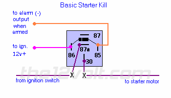
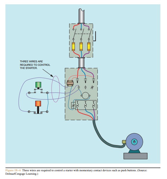
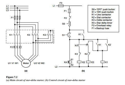
Motorcycle wiring simplified the basic diagram. In the tractor starter wiring diagram the circuit starts with the battery at the left of the. Figure 1 is a typical wiring diagram for a three phase magnetic motor starter. Have you ever flipped to the back of your motorcycle manual and looked at the stock or factory motorcycle wiring diagram. The security starter relay controlled car starter wiring diagram is as shown in the. Security starter relay controlled car starter wiring diagram.
The process for wiring a starter and an alternator on a car is divided into two parts. A typical starter solenoid has one small connector for the starter control wire the white connector in the photo and two large terminals. Wiring starter motor to switch starter motor wiring diagram. Wiring diagram consists of both examples and step by step directions that might enable you to actually construct your undertaking. Starter solenoid wiring diagram without starting relay type. The starting system circuit without starter relay set in is shown in fig.
Figure 1 typical wiring diagram. It utilizes a main tained contact type of pilot device such as a thermostat float switch or presence sensor. They can be used as a guide when wiring the controller. The second part involves the control circuits. Electrical 0 christopher pumo. The basis principles are the battery.
See how the anti.


