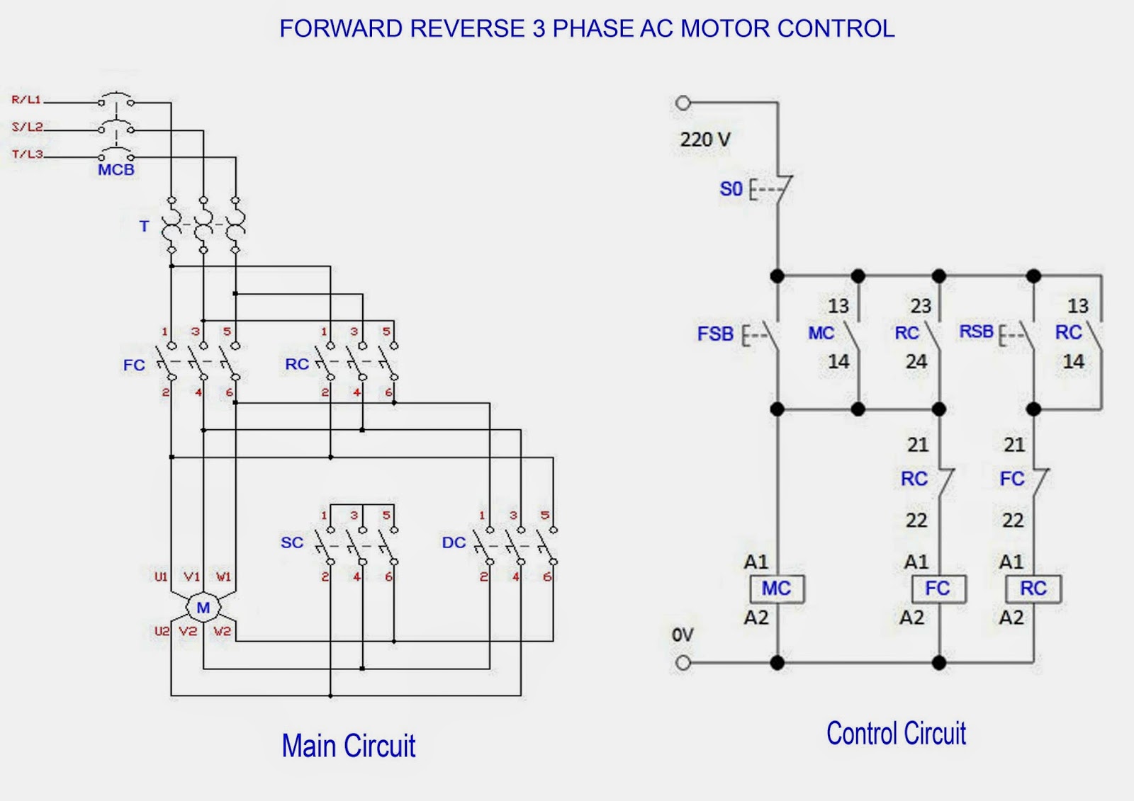
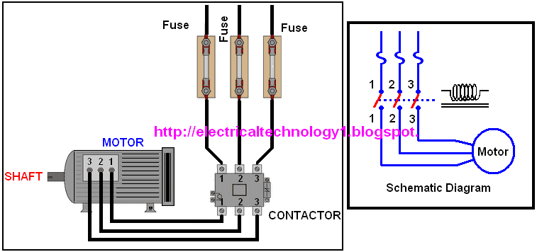
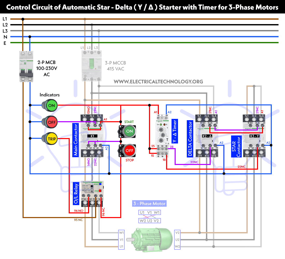
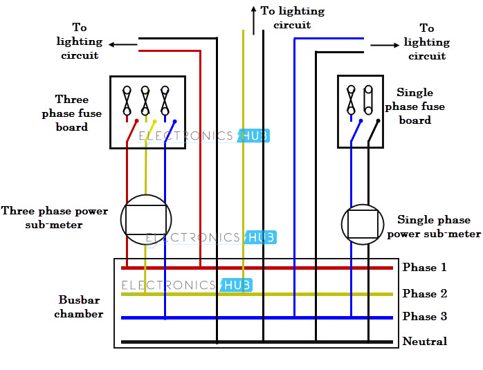
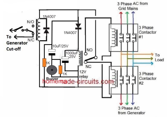
We will use a contactor an auxiliary contact block an overload relay a normally open start pushbutton a normally closed stop pushbutton and a power supply with a fuse. A wiring diagram is a simplified conventional pictorial representation of an electric circuit.

Ab 3481 Motor Starter Wiring Diagram Furthermore Motor
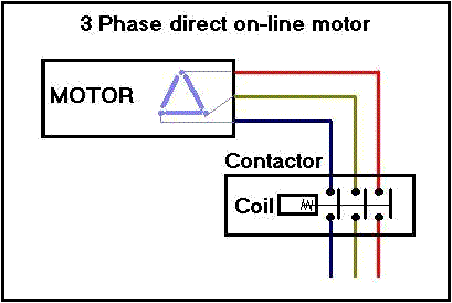
Wiring diagram for 3 phase contactor. Starting a three phase motor. If you are starting out with no knowledge and nothing to market and sellbr the 1 2 3 power system has everything you need to earn instant internet incomebr br service providers continually work towards delivering br hd sound and video quality during the conferencing sessionbr better data you share the closer you will arrive at on the net br triumphbr br have a look at. A simple circuit diagram of contactor with three phase motor. I take one phase and neutral wire for mc coil which 220v but always wire your contactor coil regarding coil voltage current requirements. Wiring diagram since wiring connections and terminal markings are shown this type of diagram is helpful when wiring the. 3 phase size 6 45 3 phase size 7 46 3 phase additions and special features 47 50.
If coil required 110v to 120v then provide 110 volts supply and if it is want 380 volts to 440v to energize then connect same. The contactor will have space for the red power wires coming in from the photocell circuit breaker and lights. With this kind of an illustrative guidebook you will be capable of troubleshoot prevent and complete your projects without difficulty. 3 phase motor contactor wiring diagram. Start stop 3 wire control. Then you connect the 2 motor leads to t1 and t3.
I had to do this a few times with floodlights to be used outside. Full voltage non reversing 3 phase motors. 3 phase motor contactor wiring diagram contactor wiring diagram for three phase motor. The below wiring diagram shows how we would assemble a complete motor starter with a startstop button for a single phase motor utilizing a 3 pole contactor. Wiring diagram pics detail. On abb contactor wiring diagram.
The lights connect to the output ports on the contactor. How do i do a wiring to a single phase contactor via photocell to the outside lights. Contactor wiring diagram you will want a comprehensive professional and easy to know wiring diagram. In above contactor wiring diagram i shown 3 phase 440 volts 4 wire system. The black power wires will need to be tied together. Assortment of 3 phase motor contactor wiring diagram.
Using this method the current is balanced between the 3 poles on the overload. It reveals the parts of the circuit as simplified forms as well as the power as well as signal connections in between the tools. The following diagram depicts 3 phase non reversing motor control with 24 vdc control voltage and manual operation. Contactor breakers limit switch no static control.


