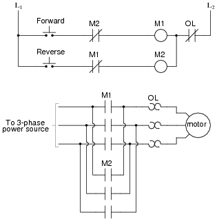
Forward reverse motor control diagram for three phase motor for three phase motor forward reverse control circuit. In this wiring diagram both the forward and reverse coils have their returns connected to l2 and not to the overload contacts.
How Can We Switch A Single Phase Motor Forward Reverse And
Forward reverse motor control diagram with timer pdf. We could replace the push button switches with. These forward and reverse starters are dol type and not used above the 05 hp motors. Wiring diagram book a1 15 b1 b2 16 18 b3 a2 b1 b3 15 supply voltage 16 18 l m h 2 levels b2 l1 f u 1 460 v f u 2 l2 l3 gnd h1 h3 h2 h4 f u 3 x1a f u 4 f u 5 x2a r power on optional x1 x2115 v 230 v h1 h3 h2 h4 optional connection. It reveals the components of the circuit as simplified forms as well as the power as well as signal links in between the tools. In short this the complete guide of forward reverse starter wiring and installation. Star delta connectiondol starter control and.
Here i showed the forward reverse wiring diagram. Figure 5 forwardreverse motor wiring diagram. If we wanted to keep the motor running even after the operator takes his or her hand off the control switches we could change the circuit in a couple of different ways. These type of starters are used in various applications eg mixing of materials dying. Forward reverse motor starter circuit क बर म जनन स पहल यह जन लन आवशयक ह क forward reverse motor क उपयग कह हत ह जब हम कह पर मटर क दन सइड घमन क आवशकत हत ह. We use 2 magnetic contactors as forward reverse switch.
To run the motor of above 05 hp rating circuit has to made in star delta. The interlock contacts installed in the previous sections motor control circuit work fine but the motor will run only as long as each push button switch is held down. In the event of an overload both motor starter output. Notice that the control section is the same as that used for reversing three phase motors. Variety of single phase motor wiring diagram forward reverse. Motor 3ct to 120 v separate control ot is a switch that opens when an overtemperature condition exists type.
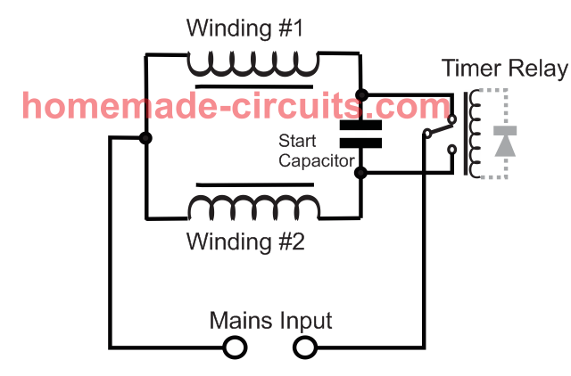
The figure given below shows the control and power diagram of forward and reverse starter diagram. A schematic diagram of a forward reverse control for a single phase split phase motor is shown in figure 2913. There is problem in control drawing because when motor runs forward or reverse then we can not change its state to forward or reverse by its push button. A wiring diagram is a simplified conventional pictorial representation of an electrical circuit. The overload contacts are connected to l1 on one side and to the plcs input module on the other input 003. The supply can not the the other conductor because nc and no both are open.
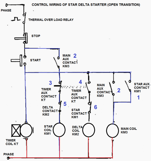
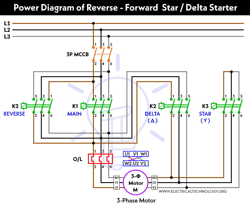
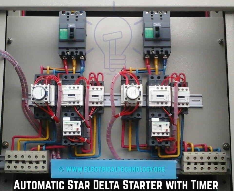
Star delta starter reverse forward power wiring connection diagramstar delta starter control circuit diagram.

