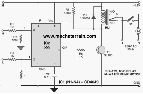
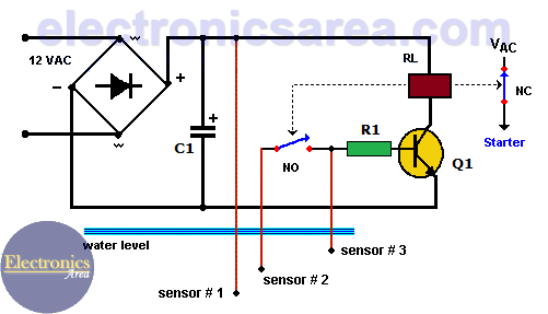
Circuit diagram circuit operation. Heres a automatic water pump controller circuit that controls the water pump motor.

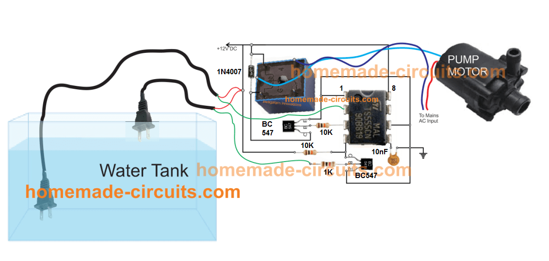
Automatic Submersible Pump Controller Circuit With Dry Run
Automatic on off switch for water pump circuit diagram. Built around only one nand gate ic the circuit is simple compact and economical. Because the base of both transistors not triggered from the common point. The circuit will automatically switch on water pump when water level in the tank reached below from the bottom level probes and automatically switch off the pump when the water level will reach at the upper level probe. Similarly it gets switched off when the tank is filled up. The figure below shows a project of a solar water pump controller circuit. To make touch switch at home httpsyoutubetd1jvdb3vs.
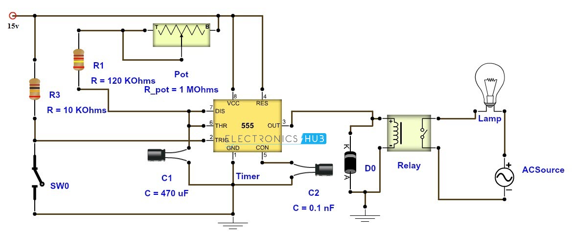
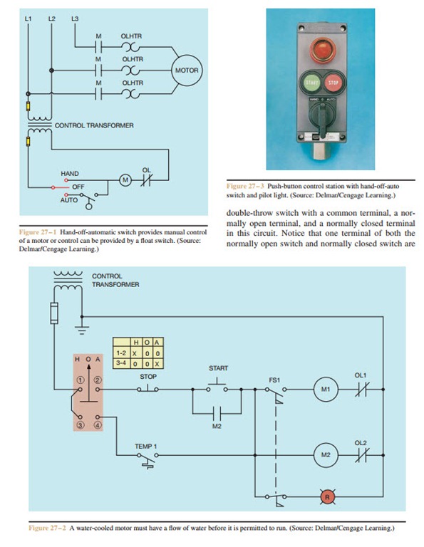
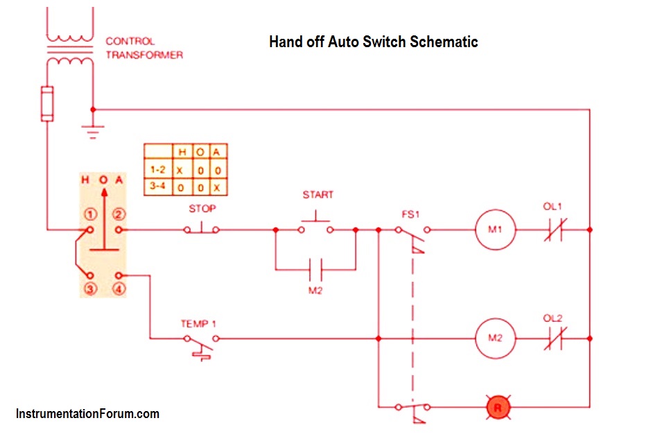
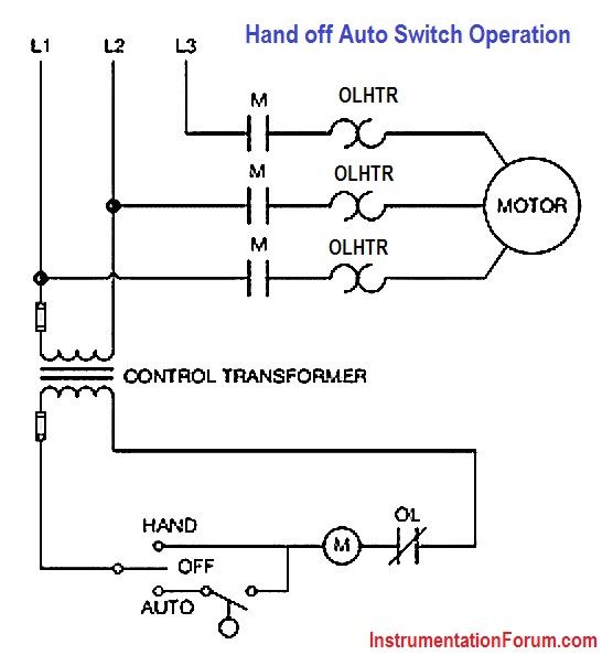
Automatic submersible motor controller project using 555 ic and relay. Hand off automatic controls are used to permit an operator to select between automatic or manual operation of a motor. The switch is shown as a single pole. You can implement this motor driver circuit at your home or college using less costly components. There are three probes in the circuit which ought to be set in the water and any thin wire will. In this section we talk about the circuit operation of an automatic water pump controller.
The circuit can be used for variety of purposes like filling pools tanks container washing machines etc. In begin states when without water on a bucket. The circuit will automatically switch on any water pump motor when the level of water in a tank reaches below from the required level and automatically switch off the pump after filling the tank. It can automatically switch on and off the domestic water pump set depending on the tank water level. Automatic water level controller circuit is a simple engineering project. The circuit is utilizing just three segments which are a 2n4401 transistor one 12k resistor and one dpdt relay.
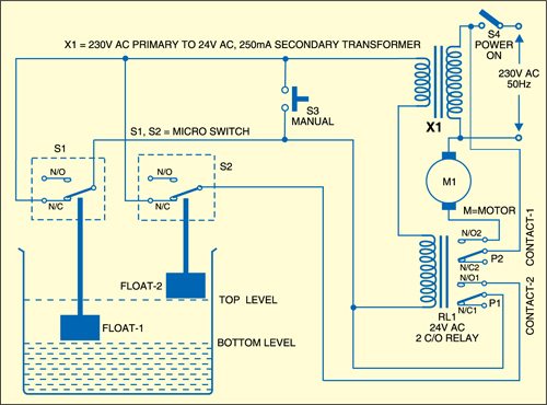
And it can not only use for controlling. Hi friends in this video im going to show you how to make automatic water pump on off circuit. Here is automatic water pump tank controller circuit diagram. The circuit shown in figure 271 permits a motor to be operated by a float switch or to be run manually. Which still connect positive voltage through r1. The motor gets automatically switched on when water in the overhead tank oht falls below the lower limit.
Hand off automatic controls recognize hand off automatic switches on a schematic diagram. This is very simple circuit diagram of water level controllerwhen water tank is full then motor pump automatic switch offautomatic water motor pump controller for overhead water tank. Both transistor q1 and q2 will not works. Water pump auto cut switch water pump auto on off switch using 4 components 1k resistor bc547 transistor 4007 diode 12v relay ir remote control on off switch circuit. As figure 1 shows automatic on off switch for water pump circuit diagram.


