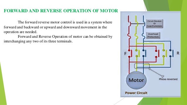
Forward reverse starter diagram. Design and construction of forward and reverse direct online motor starter abstract a direct on line starter often abbreviated dol starter is an electricalelectronic circuit composed of electro mechanical and electronic devices which are employed to start and stop an electric motor.

How To Create Relay Logic Circuit With Examples Engineer S
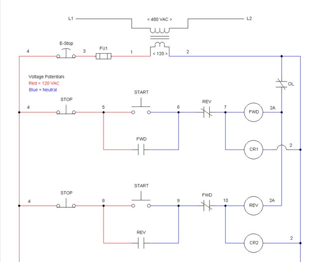
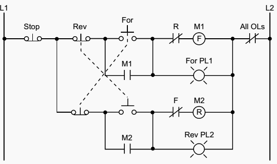
Forward reverse starter with timer. The figure given below shows the control and power diagram of forward and reverse starter diagram. Now in the below diagrams three phase motor will rotate in two directions viz forward and reverse. Also read forward reverse starter wiring diagram explained 8 pin timer wiring diagram how on delay timer works 8 pin timer diagram. As the name defines forward reverse starter is used to run the motor in both sides forward and reverse. This video is about the forward reverse starter with timer in hindi urdu. I hope after reading all the related wiring diagram with forward reverse with timer starter.
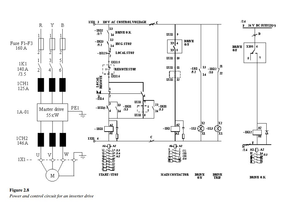
Variety of single phase motor wiring diagram forward reverse. I shown the 3 pole mccb circuit breaker 2 magnetic contactor normally open normally close push button switch thermal overload relay 3 phase 4 wire system supply 3 phase motor with connection trip indicator light etc. In short this the complete guide of forward reverse starter. In this article we are going to learn about the forward reverse starter. Three phase motor connection stardelta y δ reverse and forward with timer power control diagram as we have already shared the starting method of three phase motor by star delta starter with timer circuit power and control circuits. It reveals the components of the circuit as simplified forms as well as the power as well as signal links in between the tools.
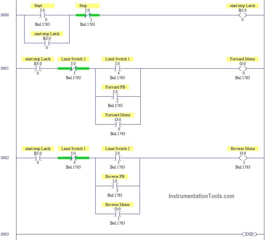
If you want need more help then also read the below post. How a star delta ic timer works. Additionally the overload light indicators have addresses 034 and 035 indicating that the overload condition occurred during either forward or reverse motor operationthe addresses for the auxiliary contact interlocking using the r and f contacts are the output addresses of the forward and reverse starters 030 and 032the ladder circuit that latches the overload condition forward or. A wiring diagram is a simplified conventional pictorial representation of an electrical circuit. The direction of rotation of any three phase motor can be reversed by changing any two motor t leads l1 figure 291since the motor is connected to the power line regardless of which direction it operates a separate contactor is needed for each directionif the l3 reversing starters adhere to nema standards t leads 1 and 3 will be changed figure 292. The control wiring of starter is shown clear to understand.
Aaj hum seke gea ke forward reverse starter ke wiring kese ke jate hai timer ke saat. In the 3 phase motor forward reverse starter wiring diagram.
