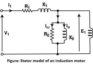
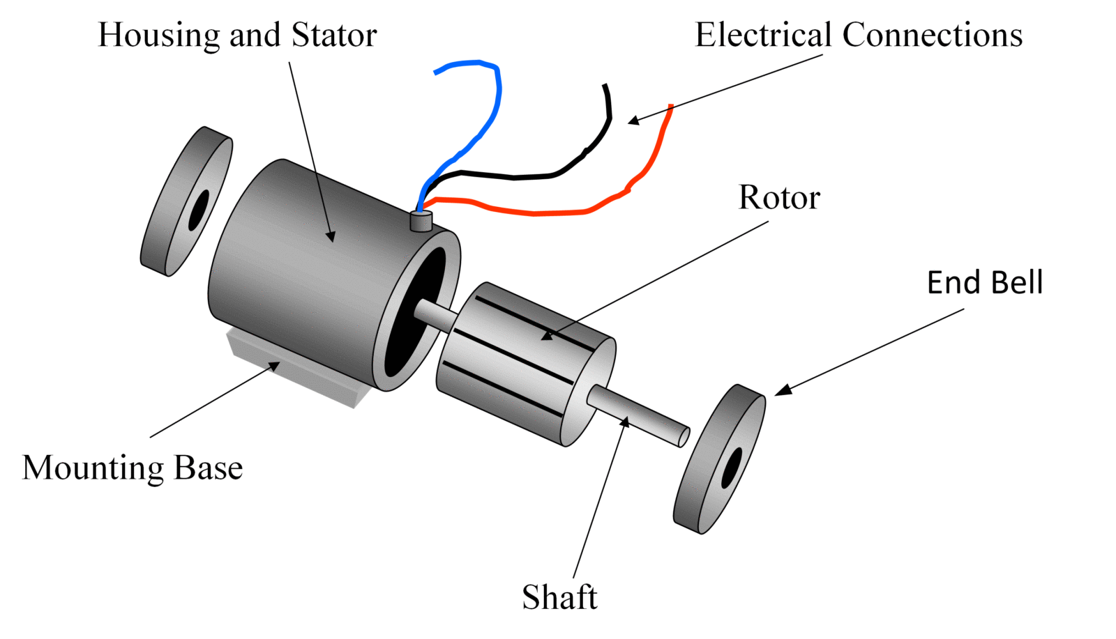
Each component ought to be placed and linked to different parts in particular manner. An induction motor or asynchronous motor is an ac electric motor in which the electric current in the rotor needed to produce torque is obtained by electromagnetic induction from the magnetic field of the stator winding.

Hmsc September 2001 Newsletter
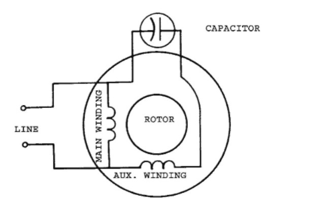
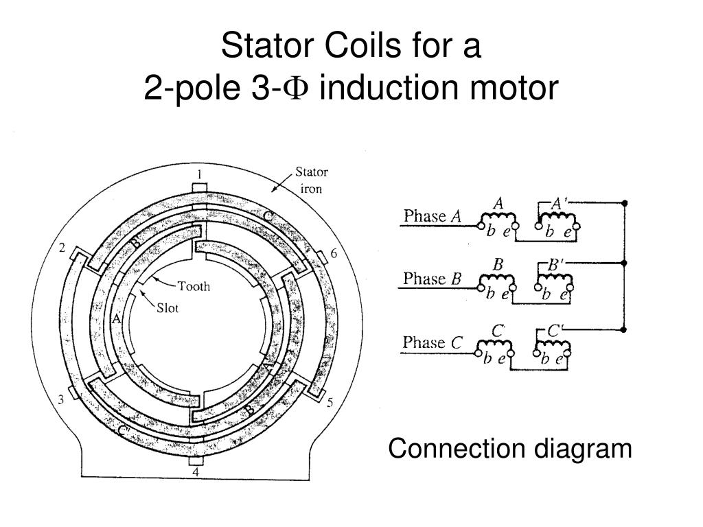
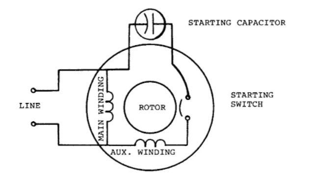
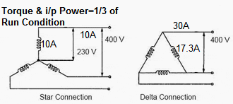
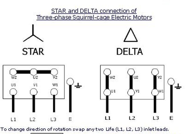
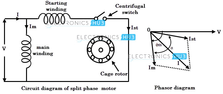
Induction motor connection diagram. How does a single phase induction motor capacitor induction motor or ac motor work. Wondering how a capacitor can be used to start a single phase motor. In this lesson well learn to read and interpret motor connection diagrams and determine the electrical relationship of the stator windings using motor connection diagrams. Electric motor wire marking connections. Learn how a capacitor start induction run motor is capable of producing twice as much torque of a split phase motor. Star connection terminal motor.
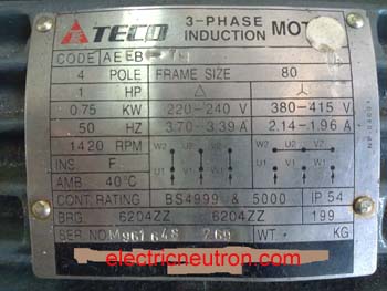
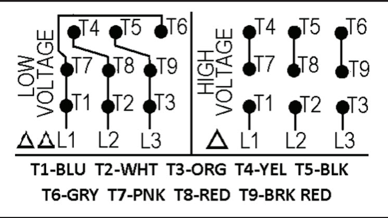
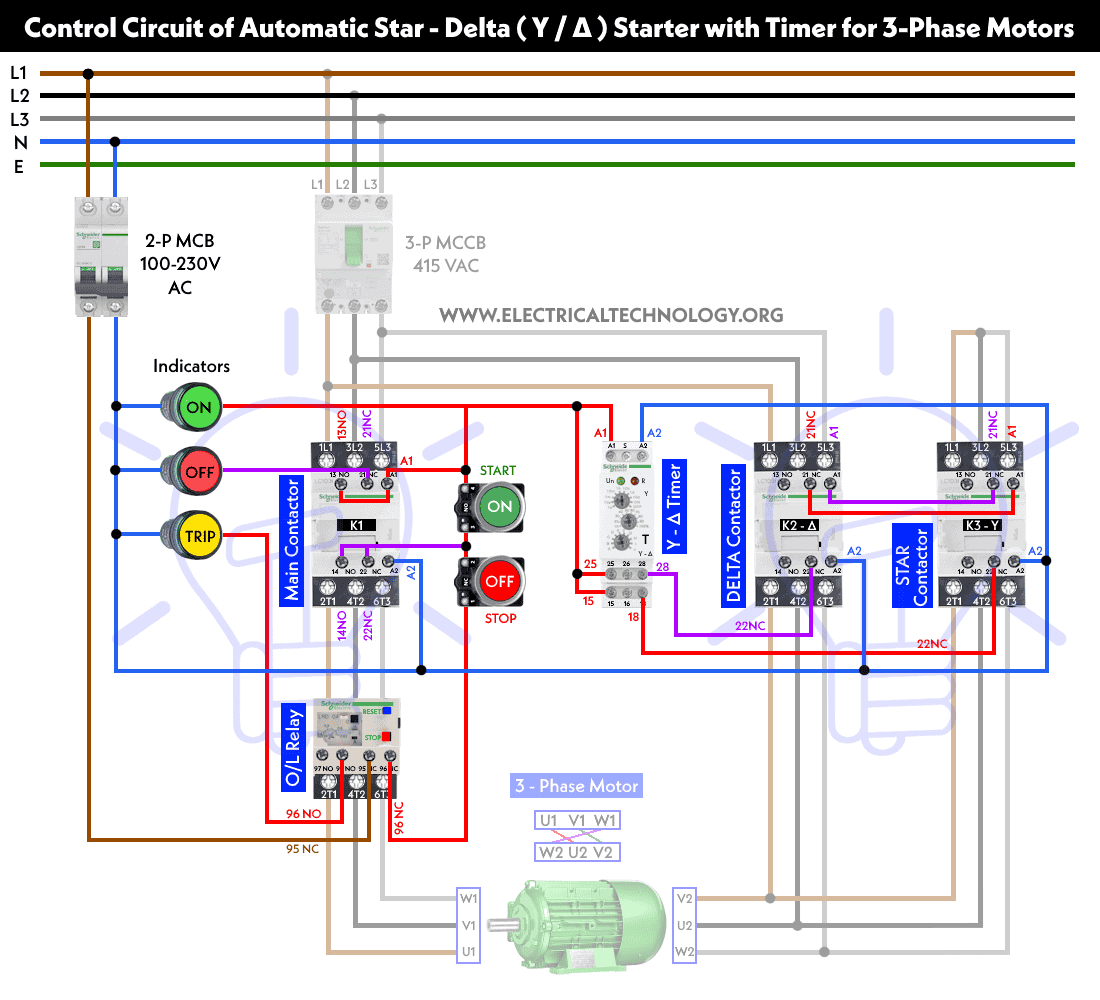
If our power supply is 200 vac 3 phasewe need to connected the cooper bar terminal in delta positionit mean a connection are u1 with w2v1 with u2 and w1 with u2it just need to follow the diagram shown in motor nameplate. An induction motor also known as an asynchronous motor is a commonly used ac electric motorin an induction motor the electric current in the rotor needed to produce torque is obtained via electromagnetic induction from the rotating magnetic field of the stator winding. Three phase see below single voltage. Single phase motor wiring diagram with capacitor baldor single phase motor wiring diagram with capacitor single phase fan motor wiring diagram with capacitor single phase motor connection diagram with capacitor every electrical arrangement is made up of various unique pieces. Connecting a 3 phase motor with 1 phase power with diagram duration. Capacitor start capacitor run induction motors are single phase induction motors that have a capacitor in the start winding and in the run winding as shown in figure 12 and 13 wiring diagram.
This type of motor is designed to provide strong starting torque and strong running for applications such as large water pumps. Delta connection terminal motor. An induction motors rotor can be either wound type or squirrel cage type. An induction motor can therefore be made without electrical connections to the rotor. For specific leeson motor connections go to their website and input the leeson catalog in the review box you will find connection data dimensions name plate data etc. Jean b 344056 views.
The rotor of an induction motor can be a squirrel cage rotor or wound type rotor. What is an induction motor. Also read about the speed torque characteristics of these motors along with its different types. Click here to view a capacitor start motor circuit diagram for starting a single phase motor.
