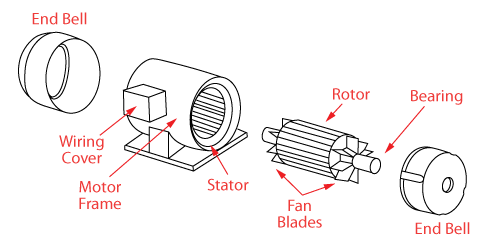
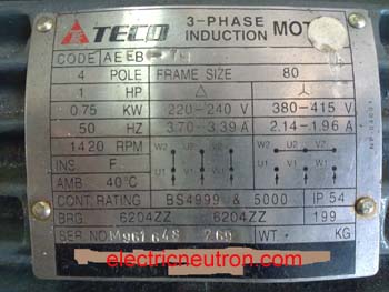
Three phase induction motor image courtesy. A three phase motor must be wired based on the diagram on the faceplate.

Wiring Connections A 3 Phase Motor Starter C3 Wiring Diagram
Three phase induction motor connection diagram. This video explains how to wire a three phase induction motor to an external electricity source. A single phase induction motor is an electric motor that operates on a single waveform of alternating current. That being said there is a wide range of different motors and what you have on hand can be completely different. Difference is that transformer is an alternating flux machine while induction motor is rotating flux machine. The three phase induction motor is the most widely used electrical motoralmost 80 of the mechanical power used by industries is provided by three phase induction motors because of its simple and rugged construction low cost good operating characteristics the absence of commutator and good speed regulation. Here i have shown the forward reverse motor control diagram for 3 phase motor.
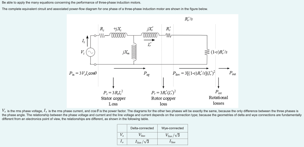
Rotating flux is only possible when 3 phase voltage or poly phase which is 120 degree apart in time is applied to a three phase winding or poly phase winding 120 degree apart in space then a three phase rotating magnetic flux is. A single phase induction motor requires separate starting circuitry to provide a rotating field to. In this lesson well learn to read and interpret motor connection diagrams and determine the electrical relationship of the stator windings using motor connection diagrams. In three phase induction motor the power is transferred from stator to rotor. Three phase wiring diagrams always use wiring diagram supplied on motor nameplate colored leads are only applicable on the new rolled steel motor lines single phase wiring diagrams always use wiring diagram supplied on motor nameplate for motors with thermal protection. Wikipedia single phase induction motors.
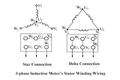
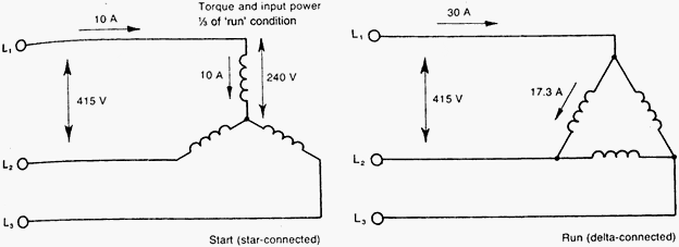
If our power supply is 200 vac 3 phasewe need to connected the cooper bar terminal in delta positionit mean a connection are u1 with w2v1 with u2 and w1 with u2it just need to follow the diagram shown in motor nameplate. Delta connection terminal motor. Star connection terminal motor. There are three basic types of small induction motors. Single phase induction motors are used in residential applications for ac motor appliances in single or multiple dwellings. Induction motor is a generalized transformer.
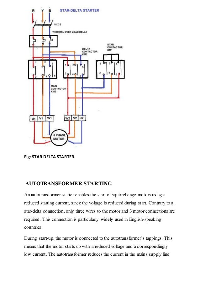
In the united states for low voltage motors below 600v you can expect either 230v or 460v. It also shows the difference between delta and star connections used to connect the motor coils. In two pole single phase motors the torque goes to zero at 100 slip zero speed so these require alterations to the stator such as shaded poles to provide starting torque. After that the three phase supply goes to thermal overload relay and from thermal overload relay the soppy goes to the 3 phase motor connection plate and provided to 3 phase motor. The first step is to figure out the voltage of your phases. Split phase single phase shaded pole single phase and polyphase.

