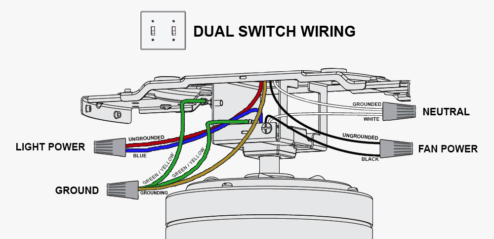
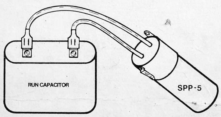
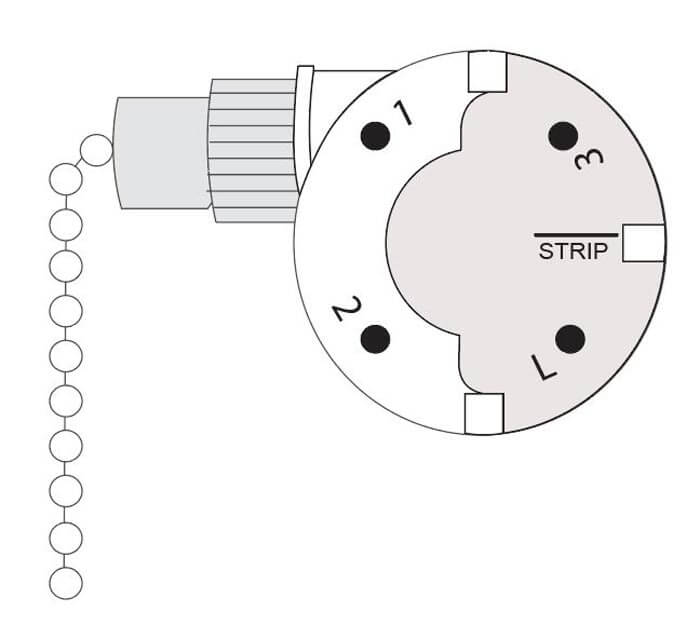
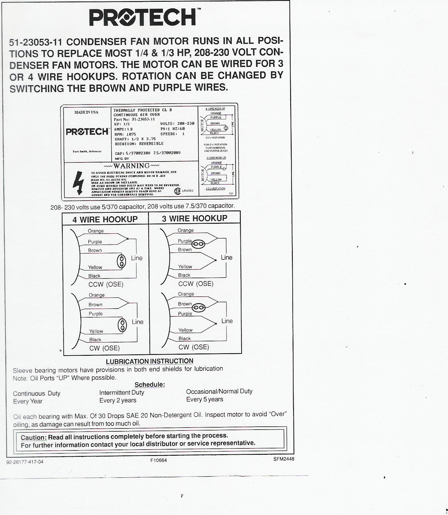
Wondering how a capacitor can be used to start a single phase motor. Ceiling fan capacitor connection internal wiring of a fan.

Ceiling Fan Capacitor Wiring Connection Diagram Ceiling Fan
Fan capacitor connection diagram. Double check your connections using the fan wiring diagrams. Learn how a capacitor start induction run motor is capable of producing twice as much torque of a split phase motor. So im thinking that the motor may have to start with the slower. Click here to view a capacitor start motor circuit diagram for starting a single phase motor. Before go in details about why a capacitor is connected in series with the auxiliary winding let is know what will happen if there is no capacitor in a ceiling fan. Ceiling fan capacitor connection diagram is too simple and easy connection but a new person cannot do it easily.
Checking the motor and capacitor connections. As it is a capacitor start capacitor run type motor. Single phase motor wiring diagram with capacitor baldor single phase motor wiring diagram with capacitor single phase fan motor wiring diagram with capacitor single phase motor connection diagram with capacitor every electrical arrangement is made up of various unique pieces. However in sha allah after this post you can do it easily. Therefore we have the method to determine it with a digital multi meter. Each component ought to be placed and linked to different parts in particular manner.
Take a look at ceiling fan capacitor connection wiring this color is not the same for all fan manufacturing company. Also read about the speed torque characteristics of these motors along with its different types. Ans as the ceiling fan has two windings one is starting winding and the other is running winding. Below is the circuit diagram of split phase induction motor in a ceiling fan clearly showing a capacitor connected in series with the starting winding auxiliary winding. But before you starting doing the ceiling fan capacitor connection or replacing the ceiling fan capacitor keep in mind that electricity is dangerous and before you start the. In the above ceiling fan capacitor wiring diagram i shown a symbol diagram of fan motor winding in which i shown start run and common wiresi connect the common wire connection with one connection connector and then i connect the run wire to the other wire connector as i shown in above diagram with blue color line.
There a capacitor is used in series with starting winding it defines the direction of rotation. It is an electrolytic capacitor. Made of silicon electrical steel sheets and winded with 9999 pure enameled copper wire fan stator is the core technology in manufacturing electric fans. Look the capacitor connection how the color of wire is used in fans output. You should see that there is a separate motor winding for high speed. The concern is that there is a capacitor for the motor.
Which are in parallel connection and capacitor is connected in series with the starting winding because as per theory it produces 90 degrees lag in voltage compared to the running winding so that there will be difference in the phase of each. Ceiling fan capacitor connection diagram. How to verify fan motor wiring connections.


