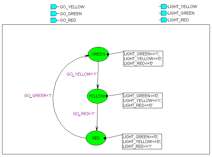
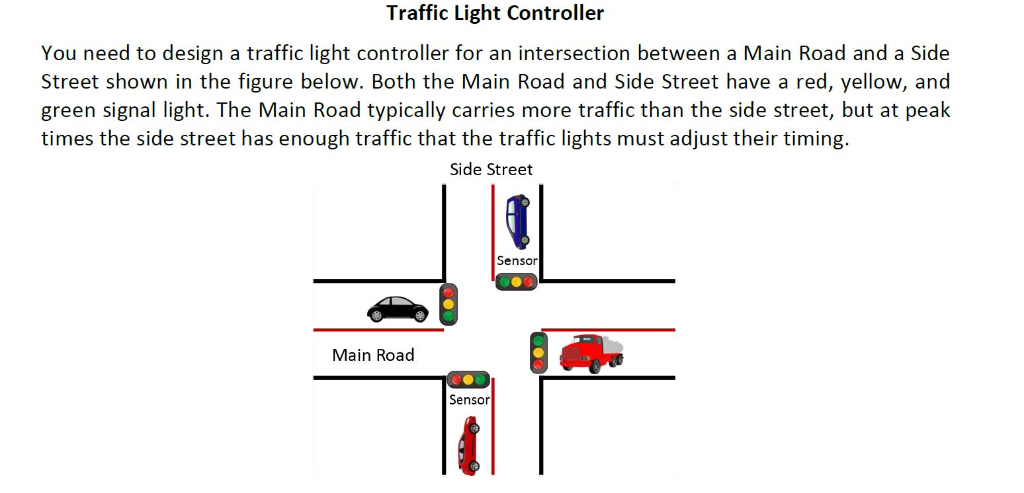
Trac light controller 1 objectives transform a controller word description into a flnite state machine fsm transition diagram. The traffic light controller in vhdl is used for an intersection between highway and farm way.

Traffic Light Wikipedia
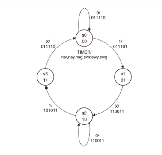
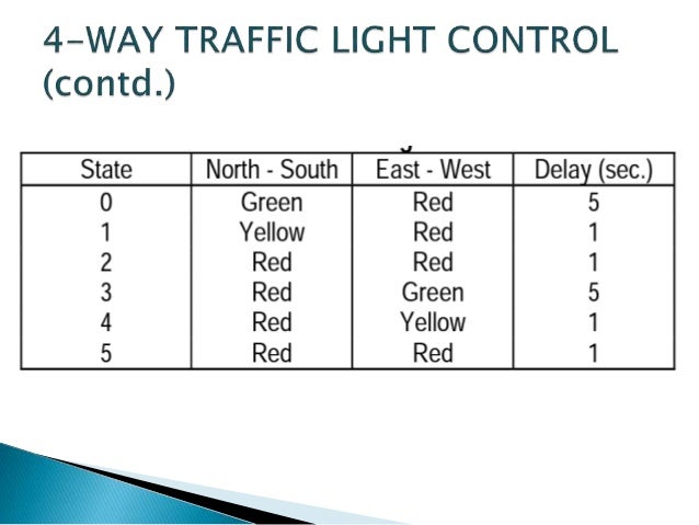
4 way traffic light controller state diagram. State table the state table is obtained from the state diagram and the states are assigned as per the table below. Traffic signal lights are very important to regulate vehicles and traffic on roads simple four way traffic light circuit is designed with timer ic 555 and counter ic cd4017. Simulate the operation of the fsm. A verilog source code for a traffic light controller on fpga is presented. Traffic light controller cont example. There is a sensor in the farm way side to detect if there is any vehicle on the farm way.
We know each traffic signal light setup will have three colors and representing red for stop yellow for wait and green for go those signals are works based on time intervals. The timer here generates pulses of time period 100ms approximately. Implement a simple flnite state machine using vhdl. Small in size only 2 12 x 3 14 inches 825 x 635 mm and programed with over 23 different sequence patterns for you to choose from for that authentic light pattern. Traffic light controller cont tabulation of inputs and outputs inputs description outputs description reset place fsm in initial state hg hy hr assert greenyellowred highway lights c detect vehicle on the farm road fg fy fr assert greenyellowred highway lights. If vehicles are detected on the farm way traffic light on the high way turns to yellow then red so that the vehicles from the farm way can cross.
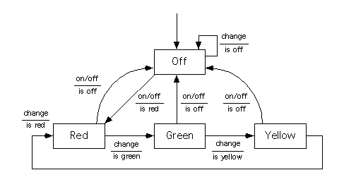
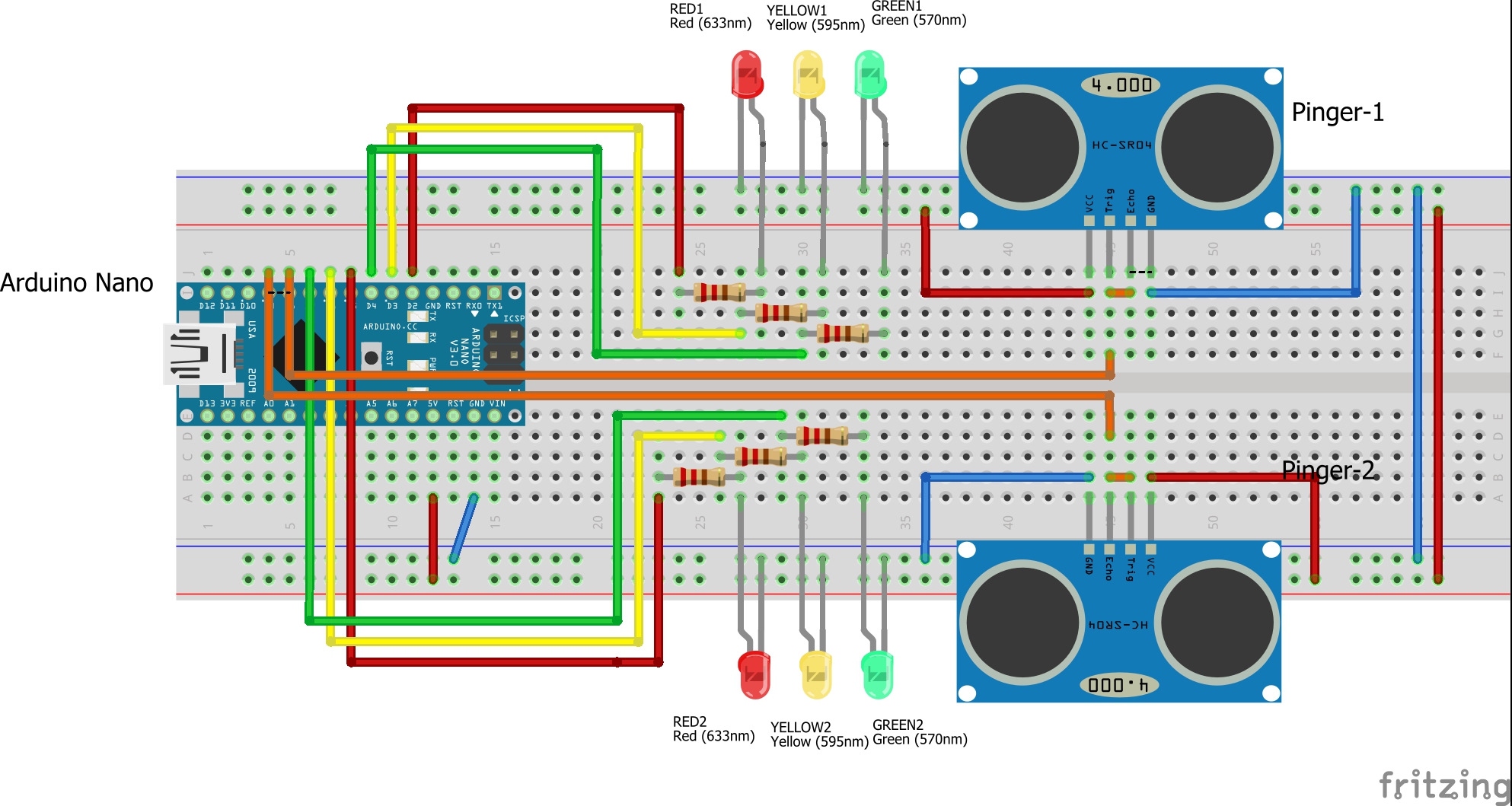
This video shows how to design the fsm state graph for the traffic light. Otherwise highway light is always green since it has higher priority than the farm. Decide which features are implemented by fsm and which features are delegated to digital logic. Installing our basic sl 3008 120 volt traffic light controller will restore full sequence operation to your light. Four way traffic light circuit diagram using 555 timer ic is shown in the above diagram. In4007 diodes 8 pieces circuit diagram and explanation.
A sensor on the farm is to detect if there are any vehicles and change the traffic light to allow the vehicles to cross the highway. A vhdl code for a traffic light controller on fpga is presented. 2 introduction the controller to be designed controls the tra. Figure 14 state diagram 5. Traffic light controller design using mealy and moore model. State binary assignment q1 q0 s0 0 0 s1 0 1 s2 1 0 s3 1.
Vuw ecs first year engineering help 15690. Red led 4 pieces blue led 4 pieces and yellow led 4 pieces cd4017 decade counter ic. This tutorial on finite state machines fsm for a traffic light controller accompanies the book digital design using digilent fpga boards vhdl active hdl edition which contains over 75. Creating traffic light controller fsm duration. 4 for simplicity only the high outputs of the respective states has been used.
