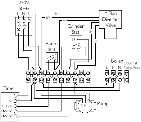
This video covers the wiring and electrical operation of an s plan system with two 2 port valves. C plan wiring.

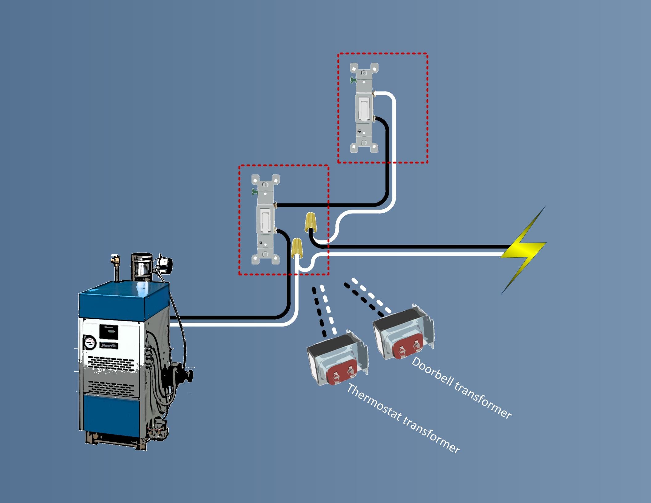
Wiring Residential Gas Heating Units
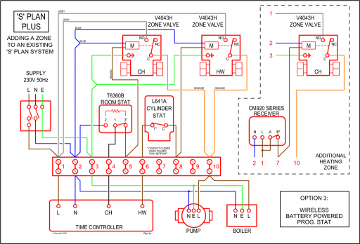
S plan boiler wiring. S plan schematic. Showing flow from boiler up to s plan valves or zone valves then onto heating and hot water circuit. Gravity hot water controlled by a 6 wire valve not your standard 5 wire valve and a pumped central heating circuit controlled by a thermostat. Part 2 in the series looks at s plan wiring a system which uses two separate valves. Electrical wiring for central heating systems. Its just a guideline on how the average boiler is wired.
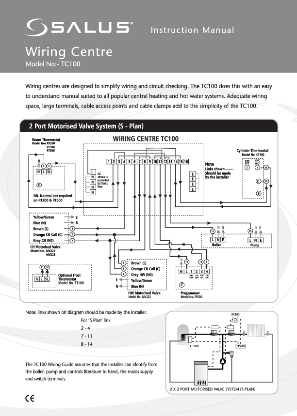
Wiring diagrams and further information continues below. S plan wiring. The diagram can be used as a boiler with a pump overrun as well you just take the pump live neutral earth from the wiring center and run it to the boiler terminals. Here coloured wires indicate the permanent mains supply to the boiler and programmer. One valve for hot water another for heating. Overview of an s plan heating system.
C plan schematic. Heated water from the boiler is diverted to the hot water coil or the radiators depending on which service the programmer is asking for and which thermostat is calling for heat. The reason this system is called a s plan heating system is because of the shape of the system when drawn schematically. W plan schematic. The s plan is popular because it is versatile you can add an unlimited number of zones simple. An s plan heating system is a system that uses zone valves also known as 2 ports s plan heating systems are now the most common type of system installed in the uk after combination boiler systems which do not have any external motorised valves.
This diagram shows the wiring layout using the most typical components. It can be adapted how you need it.


