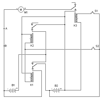
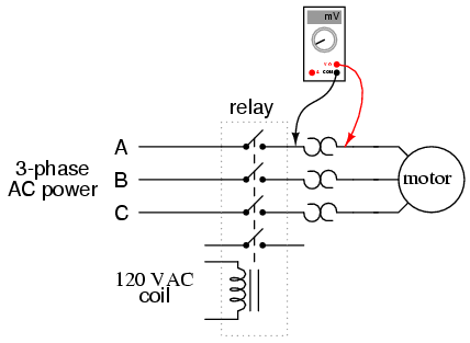
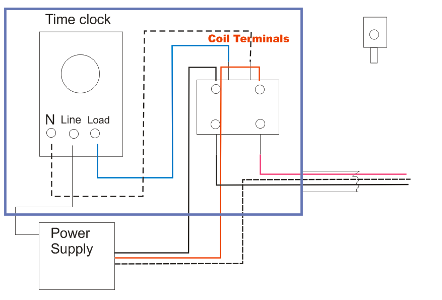
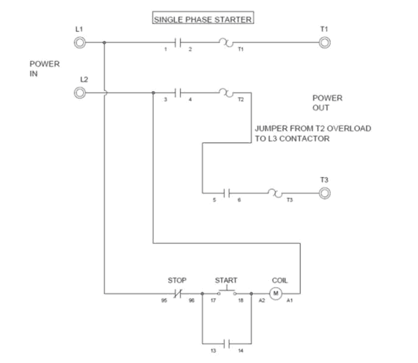
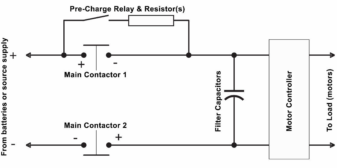
Collection of contactor wiring diagram pdf. Contactor can be removed from the starter without disconnecting any medium voltage cables.

Contactor Coil Wiring Diagram Goodman Diagram Base Website
Diagram of contactor. A simple circuit diagram. Posted january 18 by springercontrols the below wiring diagram shows how we would assemble a complete motor starter with a startstop button for a single phase motor. Either of the two start buttons will close the contactor either of the stop buttons will open the contactor. 1 less than a minute. If not the arrangement wont function as it ought to be. Posted on may 9 2018 august 9 2018 by headcontrolsystem.
Contactor wiring diagram you will want a comprehensive professional and easy to know wiring diagram. A contactor is a large relay usually used to switch current to an electric motor or another high power load. Contactor tmc 18 wiring diagram wiring a single phase motor through a 3 phase contactor. 240 volt contactor wiring diagram 220 volt contactor wiring diagram 240 volt coil contactor wiring diagram 240 volt contactor wiring diagram every electrical arrangement consists of various distinct pieces. Collection of ac contactor wiring diagram. Each part should be set and connected with different parts in particular way.
It shows the elements of the circuit as simplified forms and the power and also signal connections between the tools. Note that one one of the contactor acts as a switch for the start button. It reveals the elements of the circuit as streamlined forms and the power and also signal links between the gadgets. Collection of contactor wiring diagram ac unit. 400 ampere stab in a stab in version of the sl contactor is an available option. Contactor wiring diagram pdf download.
A wiring diagram is a simplified standard pictorial depiction of an electric circuit. How to wire a contactor. 240 volts ac and 480 volts ac are commonly used for these large pieces of. A wiring diagram is a simplified traditional pictorial representation of an electrical circuit. Many large pieces of equipment are powered directly from high voltage lines. Large electric motors can be protected from overcurrent damage through the use of overload heaters and overload contacts.
A simple circuit diagram. Contactor line and load fingers engage cell. These lines far exceed the 120 volts ac standard in most homes. A wiring diagram is a streamlined conventional photographic representation of an. With this kind of an illustrative guidebook you will be capable of troubleshoot prevent and complete your projects without difficulty. The stab in contactor is mounted on wheels and rolls into the ampgard structure.
Magnetic contactor circuit diagram luxury thermal overload relay.
