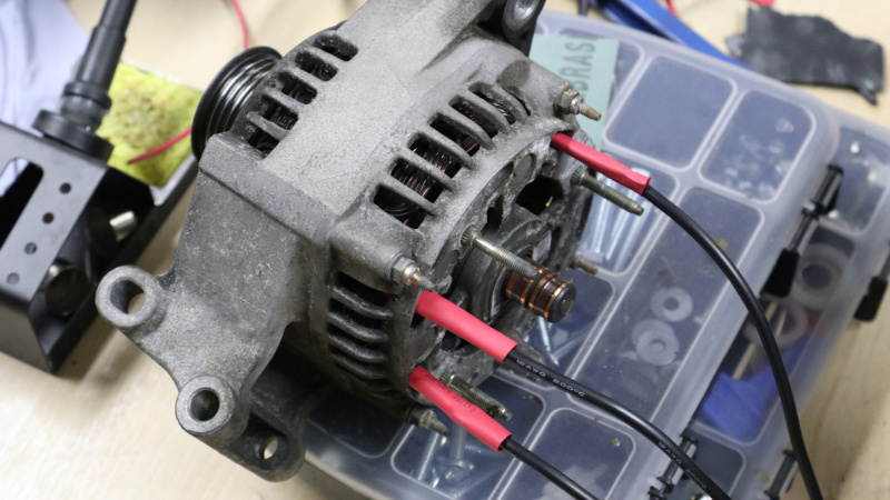
Measuring voltage 25vdc 155 degree cel. 1 is this thermistor is cutting off at 155c temperature.
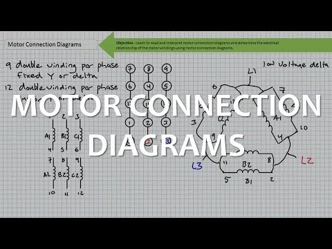
Motor Connections
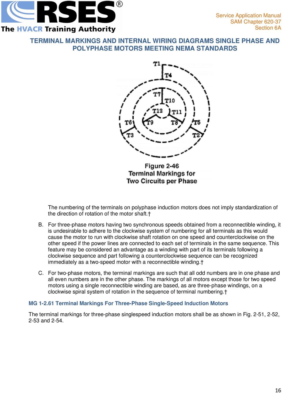
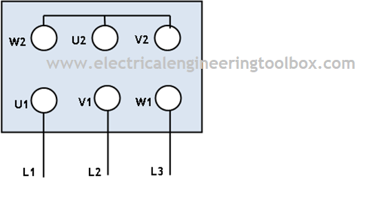
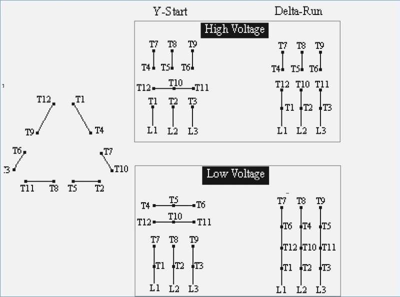
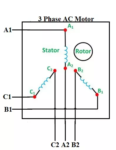
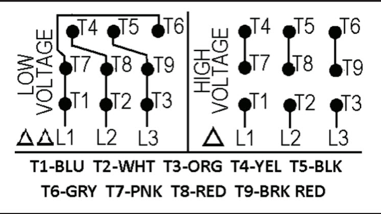
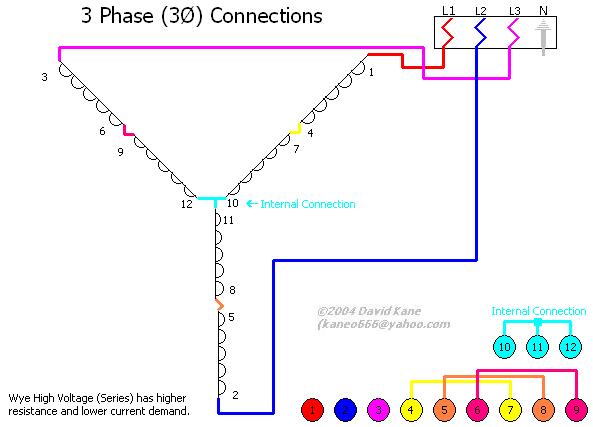
3 phase motor internal wiring. My question are. W2 cj2 ui vi wi w2 cj2 ui vi wi a cow voltage y high voltage z t4 til t12 10 til t4 t5 ali l2 t12 ti blu t2 wht t3org t4 yel t5 blk t6 gry t7 pnk t8 red t9 brk red tio curry tii grn t12 vlt z t4 til t12. For all other single phase wiring diagrams refer to the manufacturers data on the motor. Leeson motor wiring diagram leeson 1hp motor wiring diagram leeson 3 phase motor wiring diagram leeson 5hp motor wiring diagram every electric structure is made up of various distinct components. It can be used with either concentric or lap windings. Easa members can download internal connection diagrams for free.
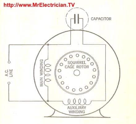
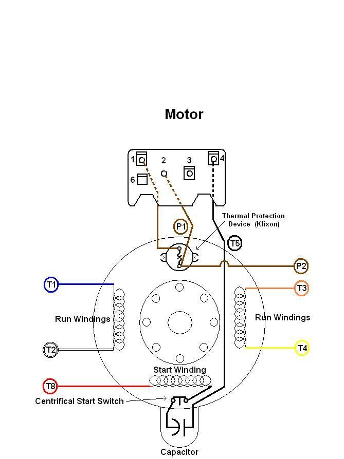
Split phase capacitor start electric motor. This edition of easa internal connection diagrams contains significantly more connections than the previous version 1982 as well as improved templates for drawing connection diagrams. For specific leeson motor connections go to their website and input the leeson catalog in the review box you will find connection data dimensions name plate data etc. Diagram dd6 diagram dd7 m 1 ln e diagram dd8 ln e l1 l2 l3 sc z1 u2 z2 u1 cap. Thermal contacts tb. Star delta y δ 3 phase motor starting method by automatic star delta starter with timer.
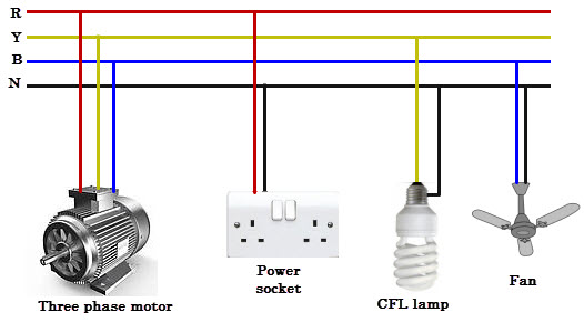
These diagrams are current at the time of publication check the wiring diagram supplied with the motor. Different regions may use different voltages. Electric motor wire marking connections. Three phase see below single voltage. They can also be found in large residential complexes and appliances requiring a large amount of power. Inst maint wiringqxd 5032008 1002 am.
It provides internal connection diagrams for three phase windings. Three phase motor connection stardelta without timer power control diagrams. See mg 1 221 mg 1 224 direction of rotation. Terminal markings and internal wiring diagrams single phase and polyphase motors meeting nema standards see fig. Hello mradward i am using a 3 phase motor weg 200kw it contain a built in winding temperature detector thermistor ptc with max. The auxiliary circuit is opened by the centrifugal switch when the motor reaches 70 to 80 percent of synchronous speed.
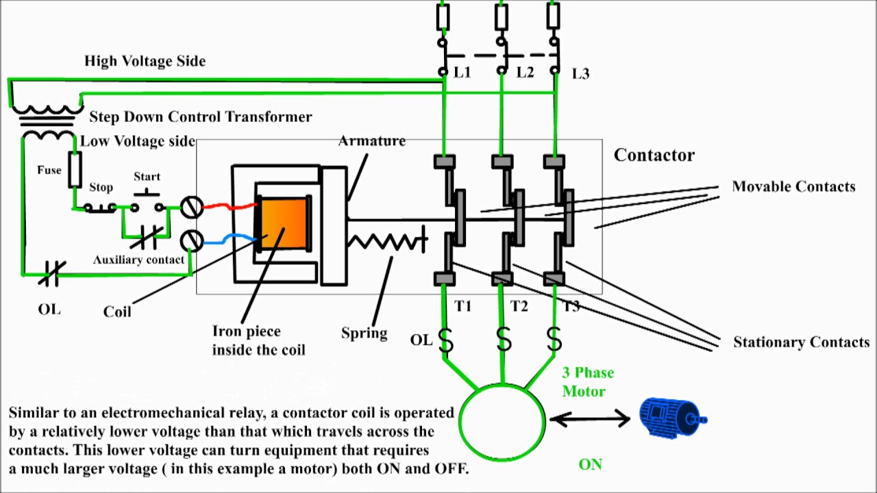
Although these systems may seem intimidating at first a walkthrough on 3 phase wiring for dummies will help clarify the whole situation. Three phase motor connection schematic power and control wiring installation diagrams. If not the arrangement will not function as it ought to be. Capacitor motor single phase wiring diagrams always use wiring diagram supplied on motor nameplate. A split phase capacitor start electric motor may be defined as a form of split phase motor having a capacitor connected in series with the auxiliary winding. Three phase systems are extremely common in industrial and commercial settings.
Each part should be placed and connected with other parts in specific way. 2 11 in which vector 1 is 120 degrees in advance of vector 2 and the phase sequence is 1 2 3. 2 is this sensor is operated normal if connect for a 20 meter cable distance.
Gallery of 3 Phase Motor Internal Wiring