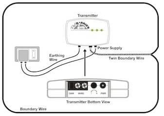
This will set the warning zone at the maximum width. Insert the boundary wires into the boundary wire terminals on the fence transmitter.

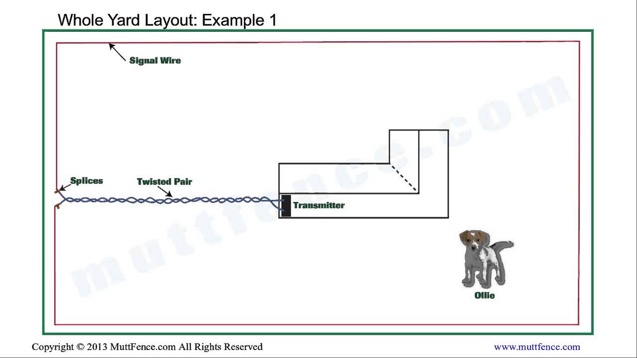
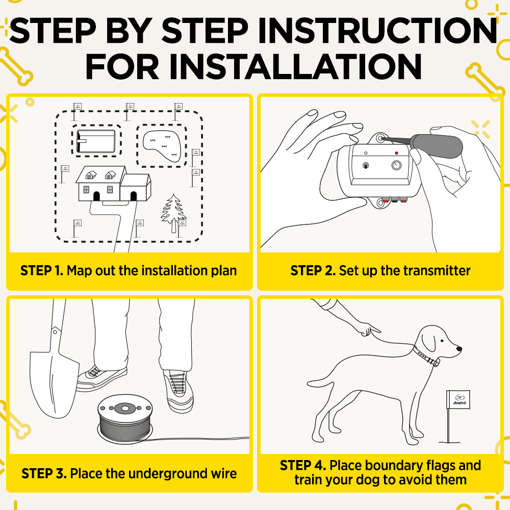
Positioning And Installing The Boundary Wire
Invisible fence transmitter wiring diagram. Page 1 ict 725 transmitter operation and installation manual made in the usa. Petsafe brand is the worlds leader in containment training and lifestyle solutions to give pet owners more great moments with their pets. Otherwise the structure will not function as it should be. The power light and loop indicator lights should come on. What would happen if twisted wire was not used to connect the main loop to the transmitter box for our electric fence installation. Install the transmitter base to the wall using four ¾ inch long 19mm 8 or 10 pan head sheet metal screws.
We suggest using our sample layouts as a guide to planning your dog fence installation. Invisible fence brand unplugging the transmitter to disarm the alarm video allows viewers to disconnect the unit without damages and avoiding the warranty in just a few simple steps. The invisible fence brand pet containment system and the lp 4100lp 4200 will function. Each component ought to be set and linked to different parts in particular way. How to install 4. Turn the boundary width control knob to 10.
Other than repairing the signal loop 7. Invisible fence wiring diagram recent circuit diagram maker and. Invisible fence wiring diagram youll need a comprehensive skilled and easy to know wiring diagram. Invisible fence wiring diagram invisible dog fence wiring diagram invisible fence ict 700 wiring diagram invisible fence ict 725 wiring diagram every electrical arrangement is made up of various unique parts. With this sort of an illustrative manual you are going to be able to troubleshoot prevent and total your projects without difficulty. Plug the power adapter into the power jack and a 120 volt outlet.
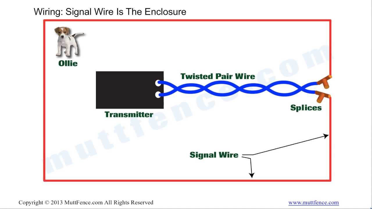
Lovely how to wire an electric fence diagram diagram wiring. Invisible fence wiring diagram free downloads invisible fence wiring. Invisible fence wiring diagram collections of wiring diagram electric fence refrence wiring diagram electric. Insert the screws through the four mounting holes shown below in the base of the transmitter case. The 12v ac transformer is plugged into the trans wire do not attempt to service any invisible fence equip mitter and is connected to a 110v ac outlet. The perimeter fence wire always needs to make a closed loop or circuit.
There are many different ways to achieve a closed loop.
Gallery of Invisible Fence Transmitter Wiring Diagram