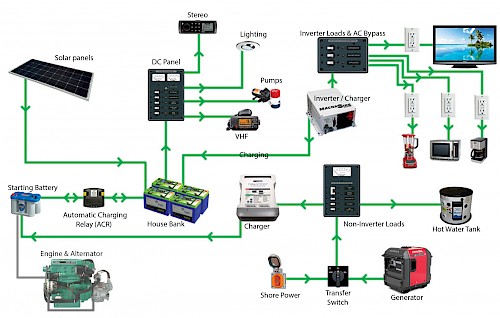
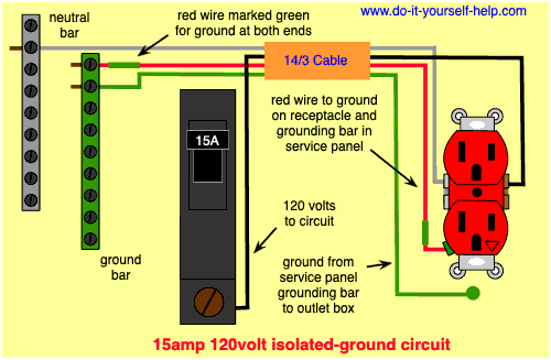
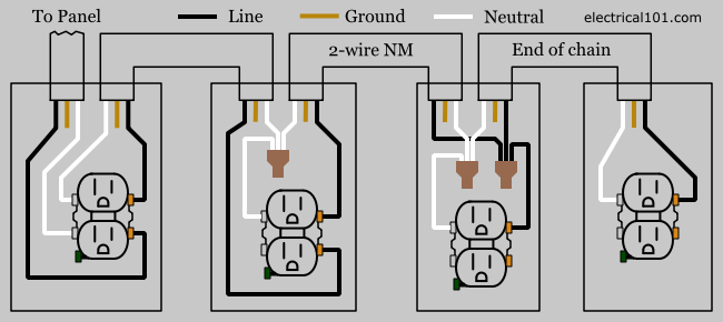
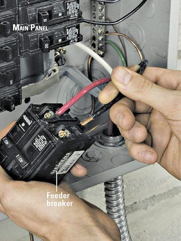
Aug 8 2016 200 amp main panel wiring diagram electrical panel box diagram. In a new home construction or a rewiring project the last step will be connecting all the wires to the circuit breaker box which is what this article describes.
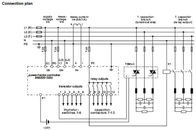
Design Electrical Wiring Diagram And Panel Design By Rambanu
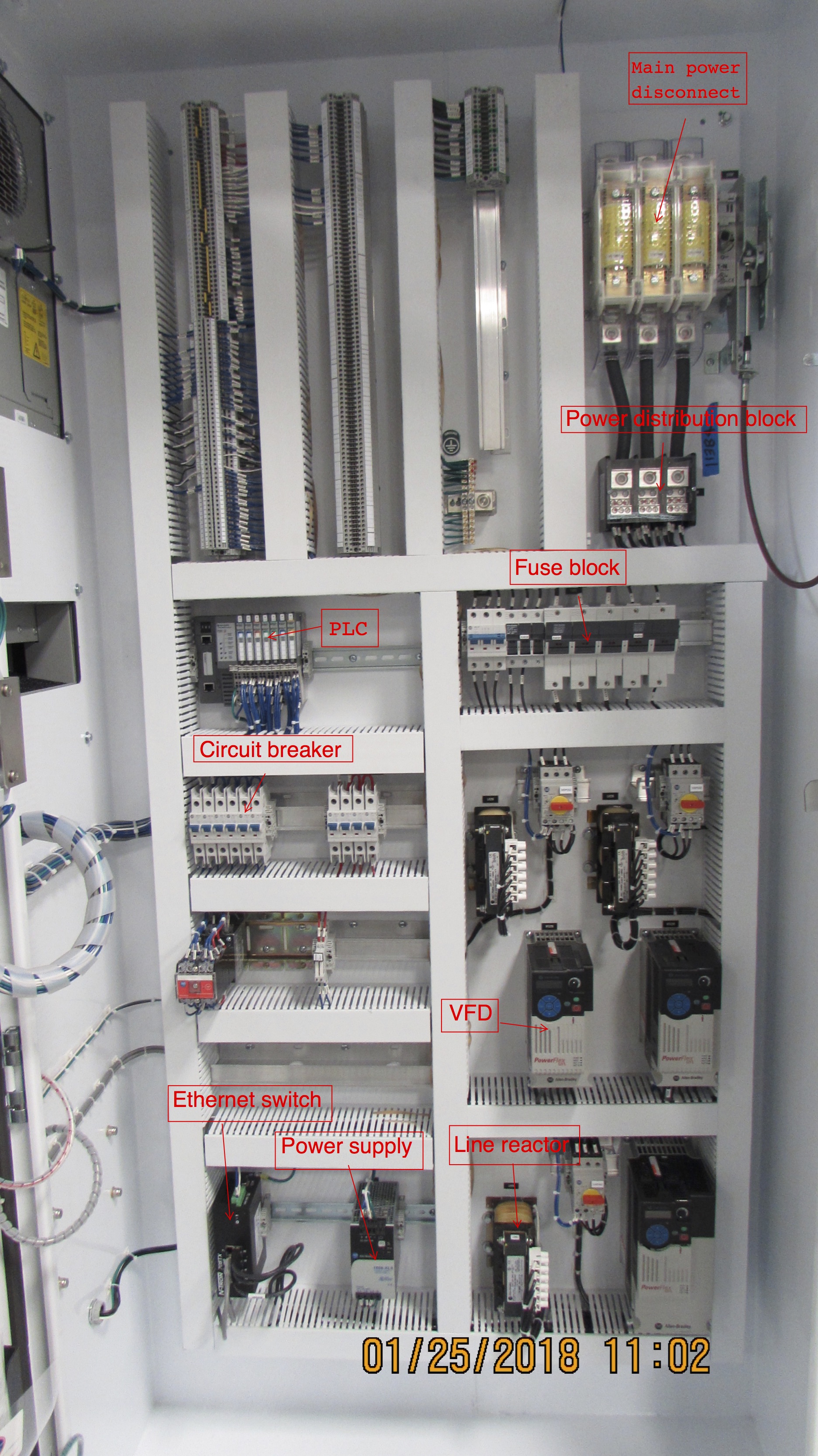
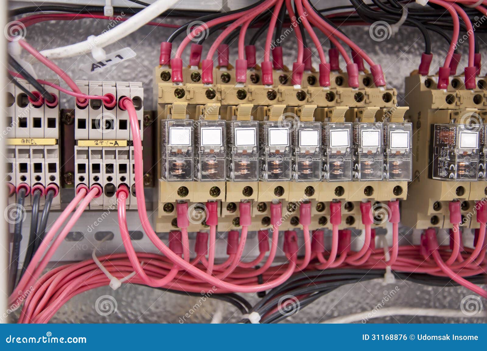
Wiring electrical panel diagram. Wiring a breaker box is a highly technical skillknowing how it operates isnt. Transformers to step down ac supply voltages to lower levels. Electrical wiring diagrams of a plc panel. Take some of the mystery out of those wires and switches that lurk behind the door of your breaker box with this. These tags can be found in the panel as well. All the wiring that you see in the panel is done based on the wiring diagram.
This is what we draw using autocad electrical. The electrical symbols will not only show where something is to be installed but what type of device is being installed. When looking at any switch diagram start by familiarizing yourself with the symbols that are being used. The electrical design for each machine must include at least the following components. Each of the wires in the wiring diagram has a tag number. This overview assumes that the electrical panel is installed on the wall of a utility area near where the main feeder wires come into the home and that all branch circuit wiring cables and conduit runs are already installed.
In an industrial setting a plc is not simply plugged into a wall socket. Each page of the wiring diagram shows the exact wiring for different sections of the control panel.

