They can also be found in large residential complexes and appliances requiring a large amount of power. Although these systems may seem intimidating at first a walkthrough on 3 phase wiring for dummies will help clarify the whole situation.

Ri Induction Motor Diagram H1 Wiring Diagram
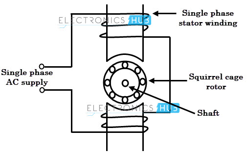
3 phase induction motor wiring diagram. It is important to point out from the phasor diagram that the phase difference between im and is is almost 80 degrees as against 30 degrees in a split phase induction motor. You may also read. Multi speed 3 phase motor 3 speeds 1 direction power control diagrams. Three phase electrical wiring installation in home iec nec. One line diagram of simple contactor circuit. How to wire a contactor and.
Three phase systems are extremely common in industrial and commercial settings. W2 cj2 ui vi wi w2 cj2 ui vi wi a cow voltage y high voltage z t4 til t12 10 til t4 t5 ali l2 t12 ti blu t2 wht t3org t4 yel t5 blk t6 gry t7 pnk. A wiring diagram of a dol starter is. A dol motor starter contains protection devices and in some cases condition monitoring. Start stop 3 wire control. How to connect a portable generator to home supply system three methods a simple circuit diagram of contactor with three phase motor.
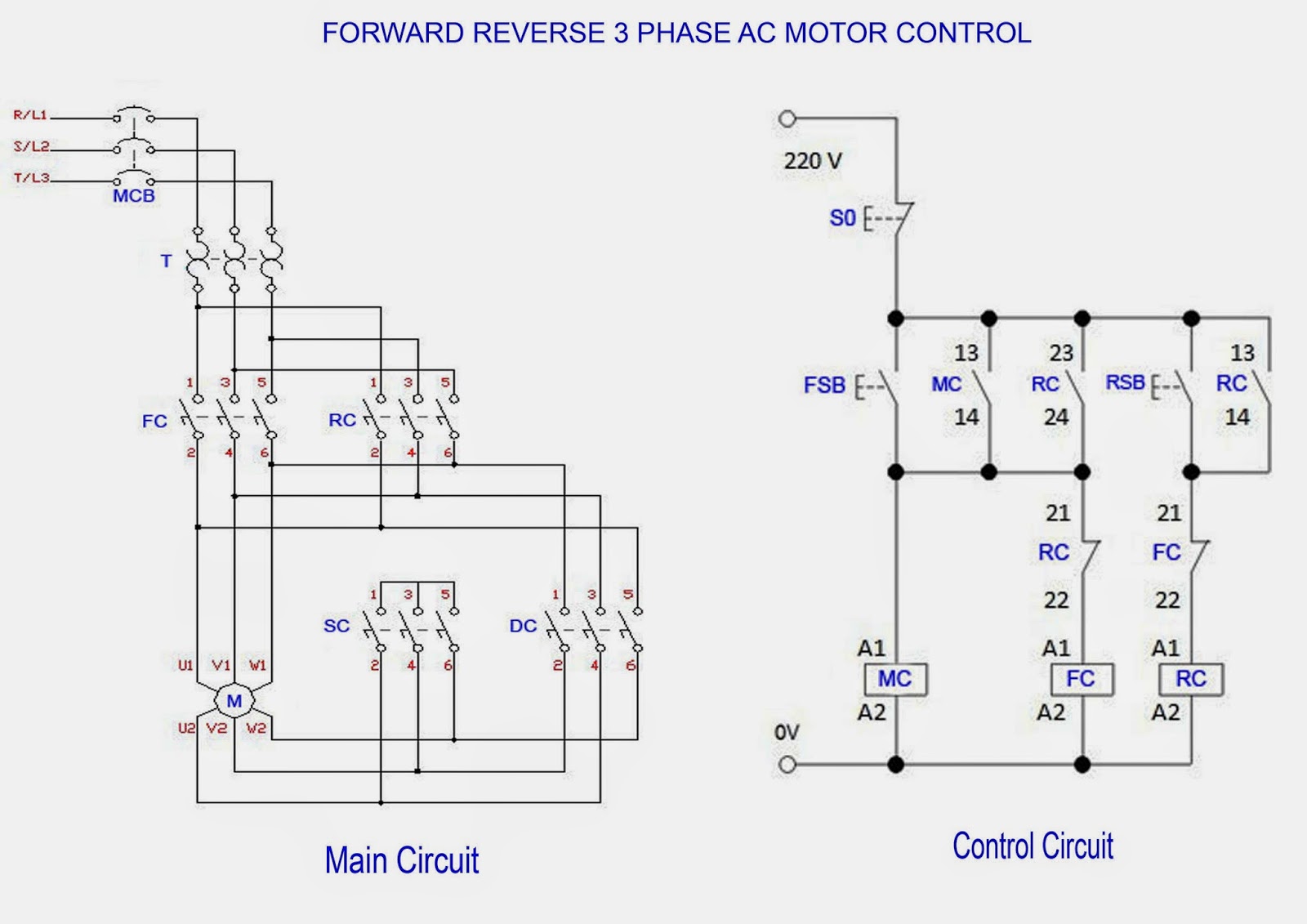
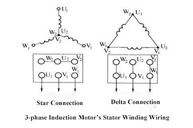
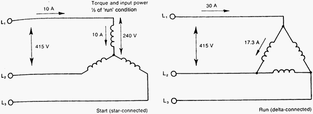
How to do contactor wiring for 3 phase induction motor with 3 pole circuit breaker overload relay nonc push button switches in this tutorial post i will tell you about motor contactor wiring and its diagram. This video explains how to wire a three phase induction motor to an external electricity source. Starting a three phase motor. 33 l1 l2 l3 n suggested wiring arrangement selector switch hi speed contactor overload overload lo speed contactor these diagrams are current at the time of publication check the wiring diagram supplied with the motor. Despite this direct connection no harm is done to the motor. It also shows the difference between delta and star connections used to connect the motor coils.
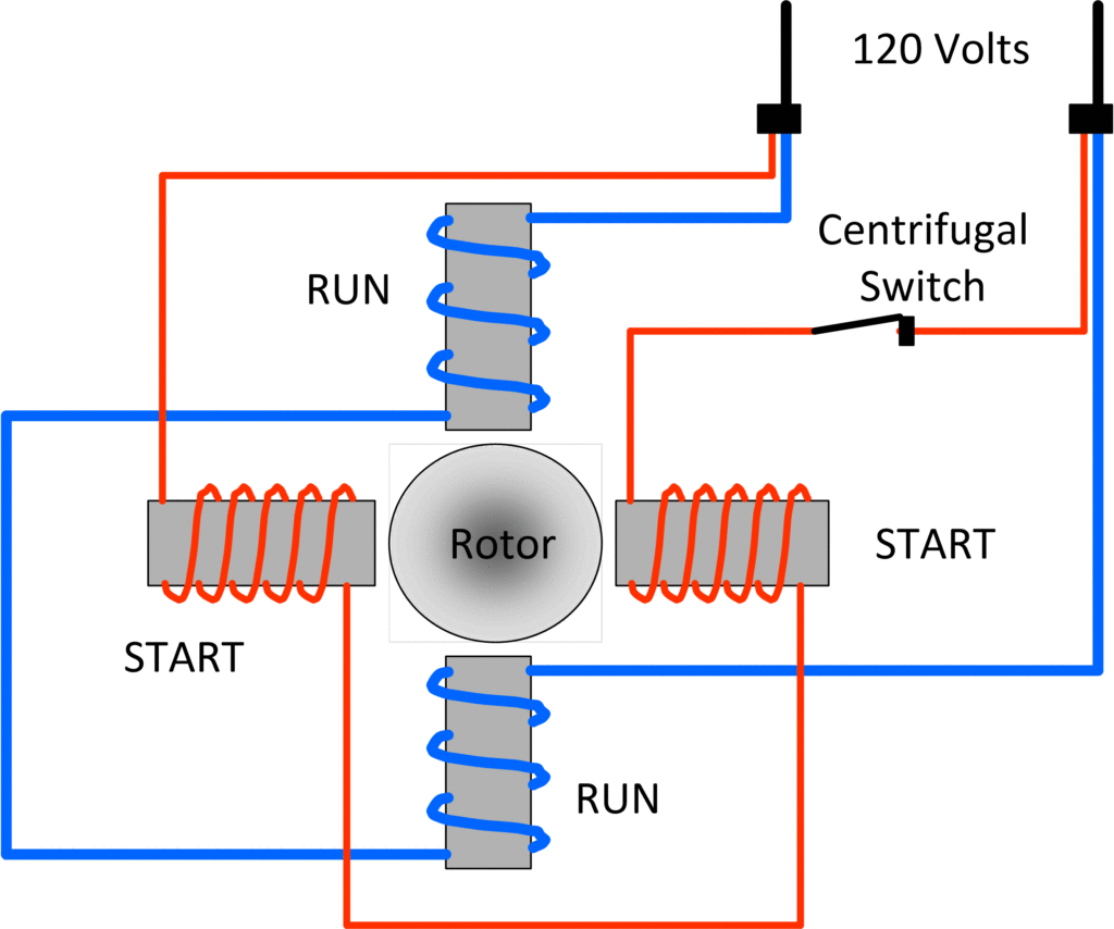
Refer to the motor manufacturers data on the motor for wiring diagrams on standard frame ex e ex d etc. Capacitor motor single phase wiring diagrams always use wiring diagram supplied on motor nameplate. In dol starter an induction motor is connected directly across its 3 phase supply and the dol starter applies the full line voltage to the motor terminals. Thus a capacitor start induction run motor produces a better rotating magnetic field than the split phase motors. Different regions may use different voltages.

.png)

