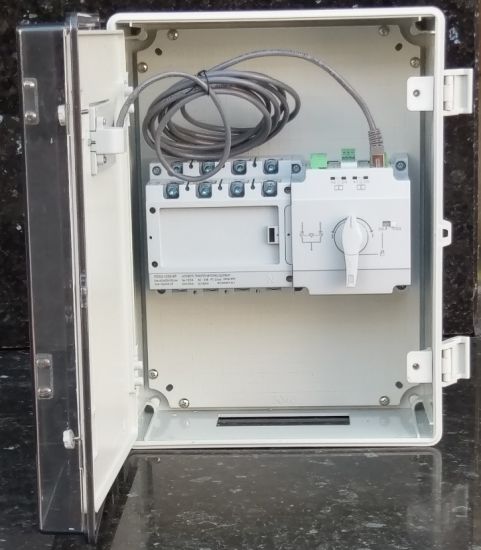
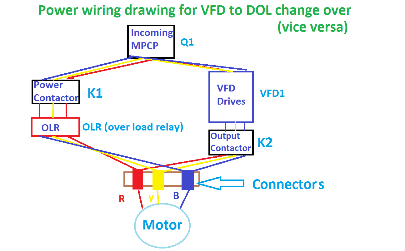
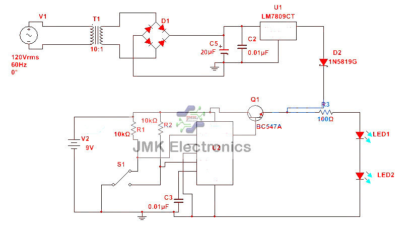
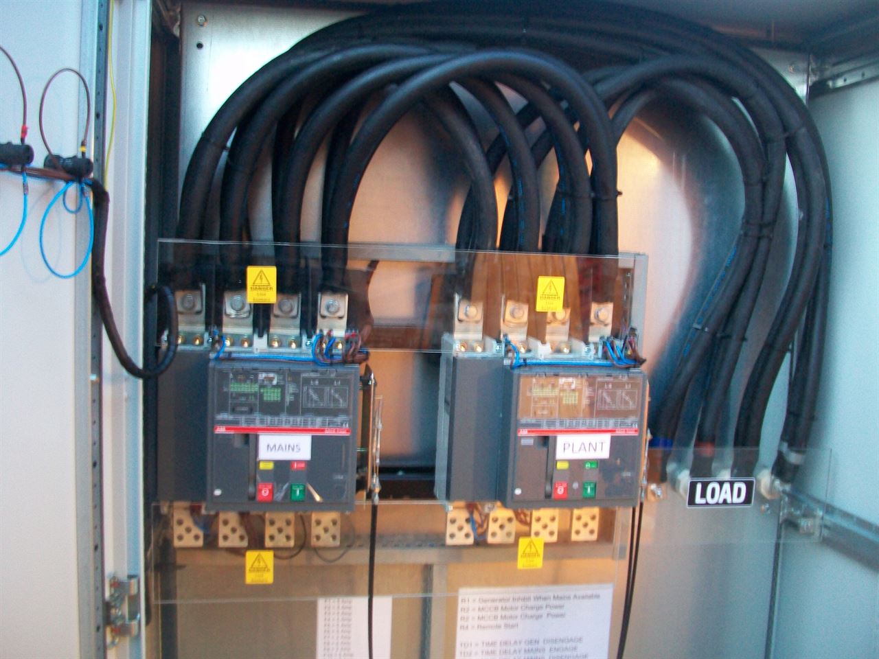
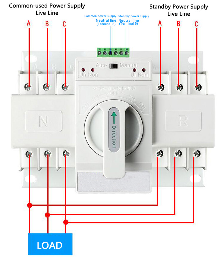
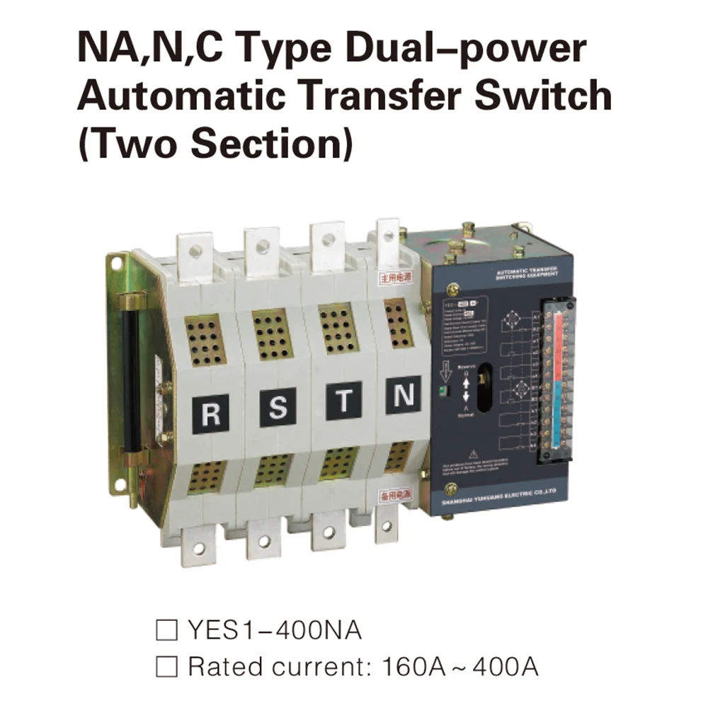
2 simple automatic transfer switch ats circuits. A contactor when closed opens its own auxiliary contact.
50amp Shorepower Installation Cruisers Amp Sailing Forums
Automatic changeover switch wiring diagram. The circuit diagram shown here is of a automatic changeover switch using ic ltc4412 from linear technologies. This is the same wiring connection as mentioned above expect automatic transfer or changeover switch instead of manual. Ups 230vac critical loads non critical loads. Compatible with abb eaton socomec motorized transfer switches. How to do rotary cam changeover switch wiring connection in urdu and hindi duration. This circuit can be used for the automatic switchover of a load between a battery and a wall adapterltc4412 controls an external p channel mosfet to create a near ideal diode function for power switch over and load sharing.
Automatic changeover switch control wiring कस कर electric guru duration. How to wire phase failure relay. A smart way to build an automatic changeover switch is by using a motorized changeover together with be28 ats controller. Socomec technologies benefits fully compliant with iec 60947 6 1 power supply taken from an existing ups load shedding principle diagram. Wiring diagram energy meter duration. This contact being in series with the coil of the other contactor will not allow the other contactor to close.
Electric guru 83391 views. In this case the two pole automatic single phase changeover or ats will transfer the power automatically from main to ups and battery in case of battery. Atys p associated to an inputoutput module can deliver a signal to the motorised switch in order to realise the load shedding. What is an automatic transfer switch and how does it work. Automatic changeover switch. Manual changeover switch wiring diagram as you know that we use generator as emergency power source in our house wiring we can do the generator changeover system in two methods in which one is manual and 2nd one automatic system.
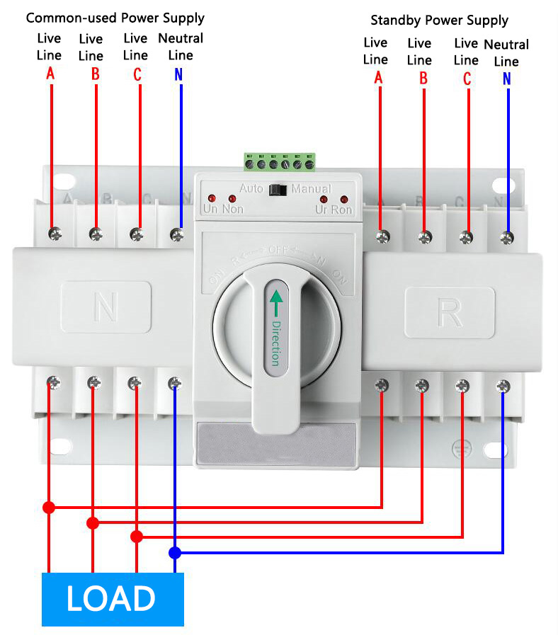
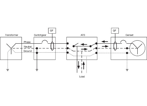
If you need a fully automatic design you can try the following circuit. Automatic changeover switch for generator circuit diagram. In this automatic changeover switch for generator circuit diagram the contactors of the generator are indicated kg and km. It is also shows the working and operation for different changeover switches wiring connections like single phase manual changeover switch with generator three phase manual transfer switch connection with generator as well as single phase and three phase automatic transfer switches connections to the 1 and 3 phase generators and main fuse board. In the first diagram the ac changeover to the load is automatic but the generator will need to be started manually by pulling the chord whenever the mains fails.
