1 lamp rapid start ballast diagram. Lamp compatibility charts wiring diagrams.

Universal Ballast Wiring Diagrams C2642unvme Universal
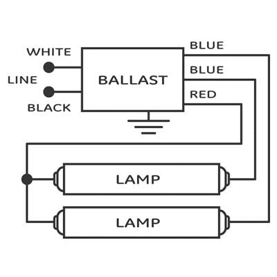
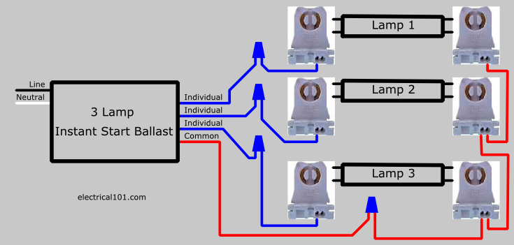
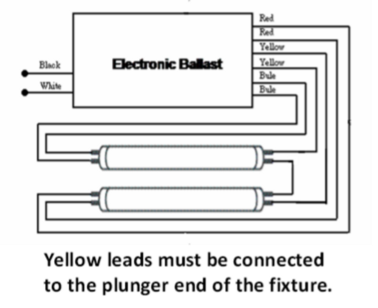
Universal ballast wiring diagram. Parallel ballasts can only be wired in parallel according to the diagram on the ballast. A member of the panasonic group and a subsidiary of panasonic lighting americas inc engineers manufactures and markets innovative solutions for commercial lighting across north america including led drivers led modules fluorescent hid and connected devices using wired and wireless technology. To aid you in a correct installation universal ballast leads are color coded for easy identification. The white ballast lead is to be connected to the neutral grounded and the black or black with white tracer lead always to the phase hot line wire. Changing the wiring on a fluorescent light fixture from series to parallel involves changing the ballast from a series to a compatible parallel ballast. Ballast case temperature can not exceed 70ºc.
A wiring diagram usually gives information approximately the relative outlook and accord of devices and terminals on the devices to urge on in building or. It shows the components of the circuit as streamlined shapes as well as the power and also signal connections between the gadgets. Universal relay wiring diagram wiring diagram is a simplified normal pictorial representation of an electrical circuitit shows the components of the circuit as simplified shapes and the gift and signal friends amid the devices. A wiring diagram is a streamlined standard pictorial representation of an electric circuit. Variety of 2 lamp t8 ballast wiring diagram. Polarity refers to the proper connection of ballast lead wires to line wires.
Remote mounting distance varies with lamp type. Universal voltage 120 277v workhorse ballast. Universal lighting technologies inc. Universal voltage 120 277v workhorse ballast lamp compatibility charts wiring diagrams.
Gallery of Universal Ballast Wiring Diagram