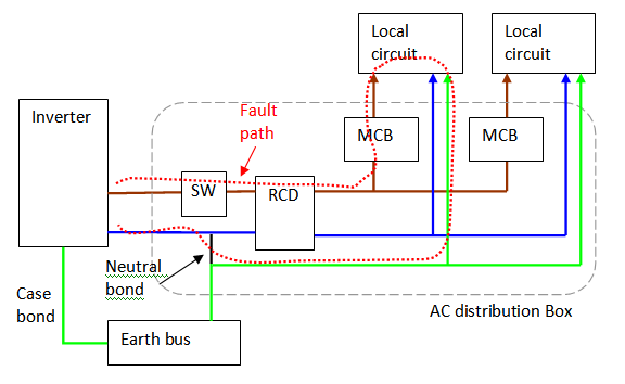
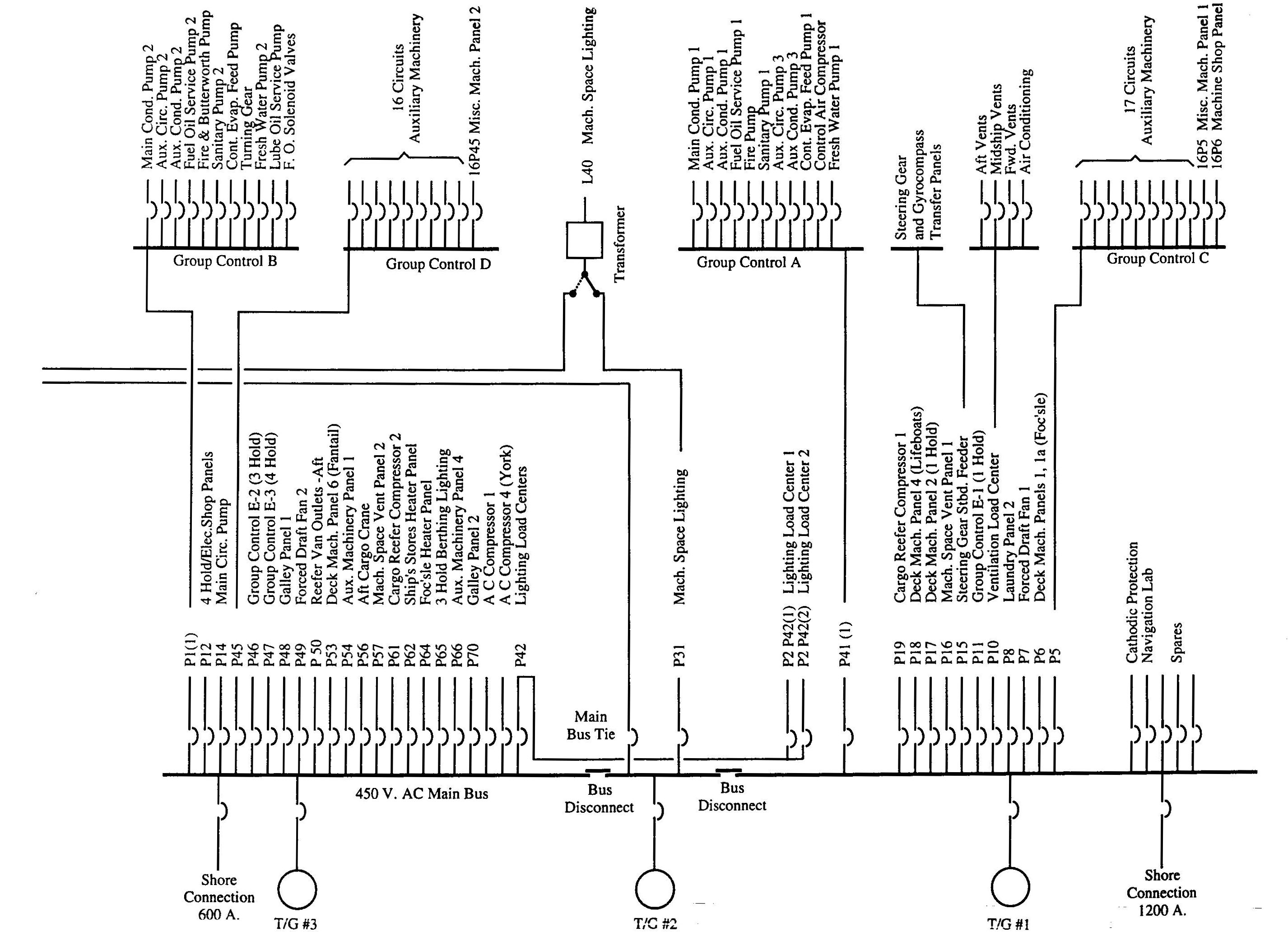
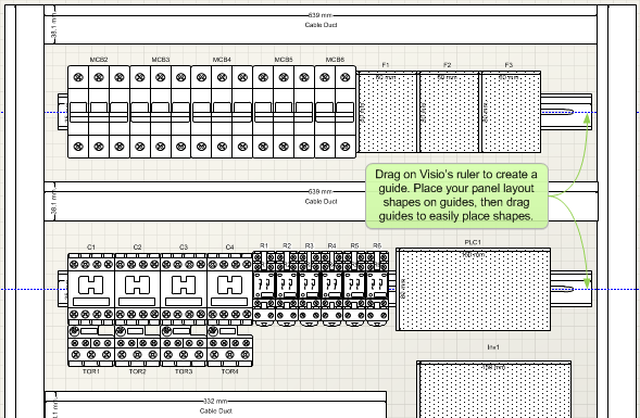
The electric main supply 230v ac 120v ac in us is connected through secondary of the transformer 3 phase 4 wire. A wiring diagram is a simple visual representation of the physical connections and physical layout of an electrical system or circuit.
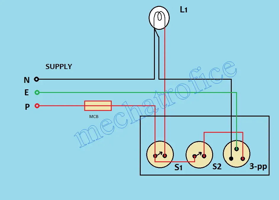
How To Wire A Switch Box Electrical Switch Board Connection
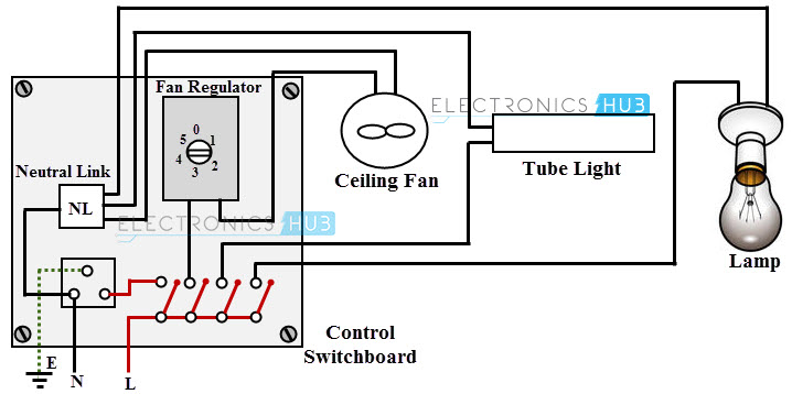
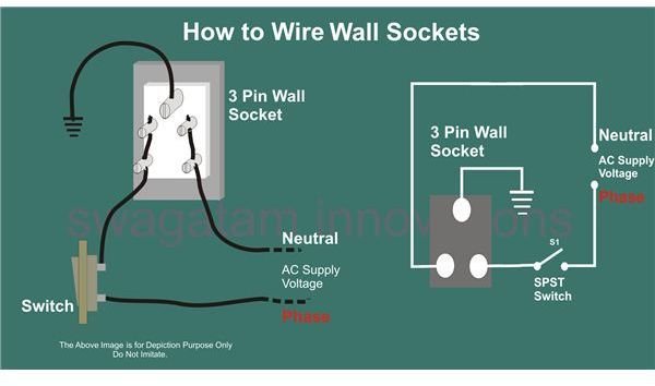
Wiring diagram of switch board. Mercury outboard ignition switch wiring diagram. How to wire a distribution board. The following explanation will help you understand better how to design home wiring layouts. One of the most complicated wiring configurations is a 4 way switch. It shows the parts of the circuit as streamlined shapes and the power and also signal links in between the gadgets. The schematic diagram for a control switch board is shown in below figure in which ceiling fan fluorescent lamp and light bulb are controlled by appropriate switches.
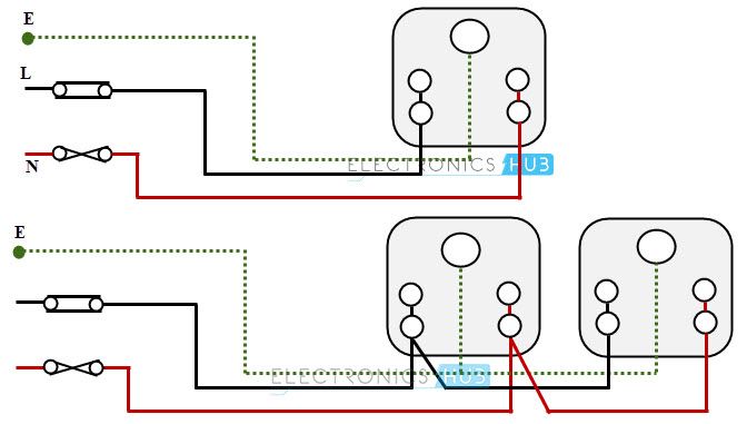
The hot and neutral terminals on each fixture are spliced with a pigtail to the circuit wires which then continue on to the next light. Typical australian domestic switch board domestic switchboard wiring. How to wire a switch and a load a light bulb to an electrical supply. September 7 2018 by larry a. Electric board wiring connection socket switch indicator lampfusefan pointlighting point 7 way board please subscribe my new channel electricalelectronics diagram. It shows how the electrical wires are interconnected and can also show where fixtures and components may be connected to the system.
Designing home wiring layouts. As can be seen in the diagram the wiring is pretty simplethe phase is invariably applied to one terminal of the switch the other terminal moves to one of the connections of the load and the other. This diagram illustrates wiring for one switch to control 2 or more lights. Without a switch wiring diagram it can be very easy to make a serious mistake that will cause the circuit to malfunction and possibly become a hazard. Universal ignition switch wiring diagram page 1 iboats re universal ignition switch wiring diagram you are probably looking at ignition switches for an i o outboard switches require more and different ignition coil troubleshooting tips for mercury mariner mercury mariner ignition coil diagrams coil packs and repair manuals troubleshooting tips. These switches enable you to control one or more fixtures from.
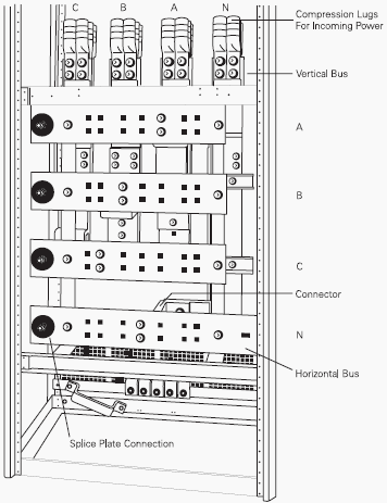
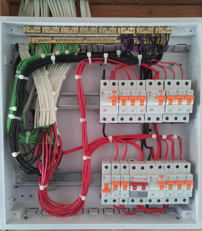
Wellborn collection of evinrude ignition switch wiring diagram. Multiple light wiring diagram. The source is at sw1 and 2 wire cable runs from there to the fixtures. Distribution board aslo know as panel board switch fuse board or consumer unit is a box installed in the building containing on protective devices such as circuit breaker fuses isolator switches rcds and mcbs etc. A wiring diagram is a streamlined conventional photographic representation of an electric circuit. Different types of semiconductor devices.
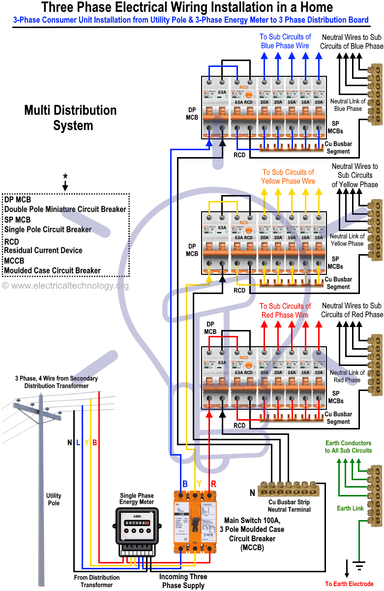
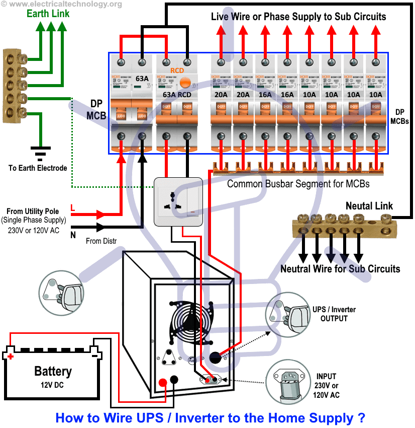
How a 2 way switch wiring works. More about 3way switch diagrams. Wiring diagram of single phase distribution board with rcd in nec us iec uk eu electrical wiring color codes double pole mcb dp the isolator or main switch this is the main operating switch which is used to control the electric power supply in the buildings. Control switch board wiring.
