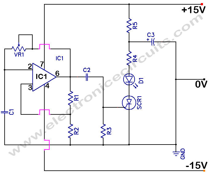
This current is given to the inverting input of 3130 ic which will get triggered by this current and give amplified output. So it works like a toggle switch.

Ir Infrared Remote Control Switch Circuit And Applications
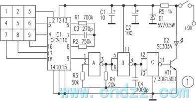
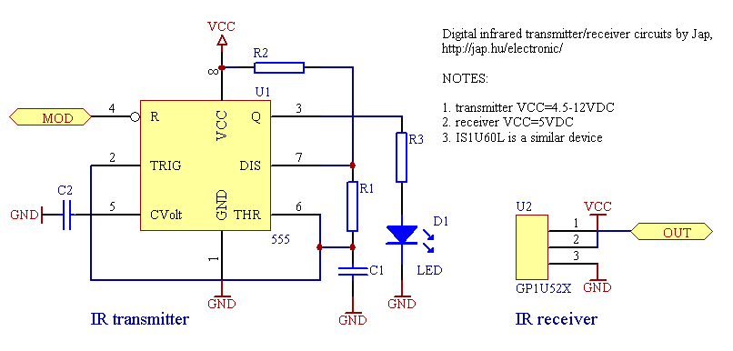
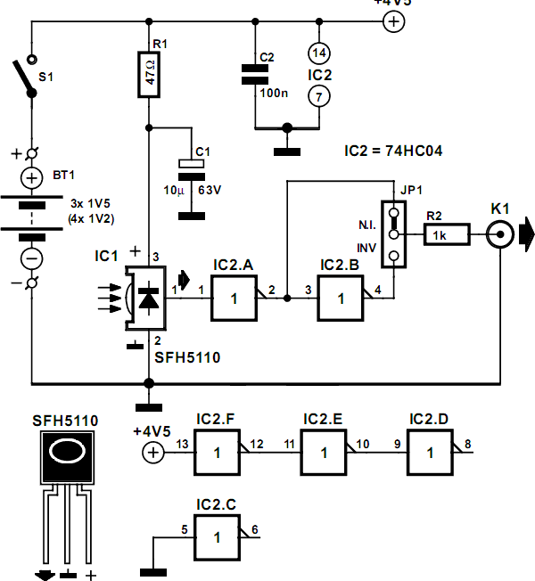
Ir remote control switch circuit diagram. In the receiver section there are 3 photodiodes which will detect the infrared signals from the receiver and produce leakage current to the capacitor c1. Circuit diagram of infrared remote control switch. Normally we use remote controls to turn on or off appliances like tv dvd player music. The infrared remote control switch is divided into two sections. Because q2 is connected to the reset pinpin 15 of 4017 it will reset the ic and again output at q 0zero becomes high and q 2 becomes low initial state. We used a simple remote and tsop 1738 ir receiver at the transmitter and receiver side of the circuit.
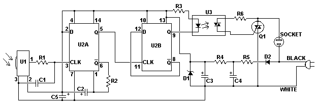
Transmitter section and receiver section. This is a schematic circuit diagram of a remote controlled switch for home appliances. The proposed infrared or ir remote control circuit can be used to operate an appliance onoff through any standard tv remote control handset. The main components of this ir remote control switch are ca 3130 operational amplifier and 4018 counter. This will deactivate the relay and switch off the light. The ca 3130 op amp is a bicmos operational amplifier and it has a high input impedance a low input current and a high speed performance.
In this remote controlled switch circuit we are using tv remote to onoff the ac light by pressing any button of remote and using the tsop1738 at receiver end. We uses normal switch in our daily life and after a long time used to these swithing system we can no more interested in that. Dosto is remote control switch ko aap kisi bhi ir remote se on ya off kar sakte haimaine is circuit board ko apne room me light ke sath connect kiya hai jo ki kafi acchi tarah se 15 meter ki doori se control ho jata hai. Tsop1738 used in the circuit for detecting ir signals from the remote. Ir remote control circuit diagram. This circuit works with any infrared remote using for tv dvd usb player etc.
Ir remote controls switch circuit. Remote controlled switch this is the very simple circuit diagram of ir remote control switch. Receiver circuit is connected to ac appliance via relay so that we can control the light remotely. We have used ic 4017 to convert it into a push on push off switch. In this write up we discuss a couple of these simple infrared remote control circuits designed for controlling any given electrical appliance through an ordinary or tv remote control unit. Remote controlled light switch is an application where a remote is used to turn on or off an ac light.
