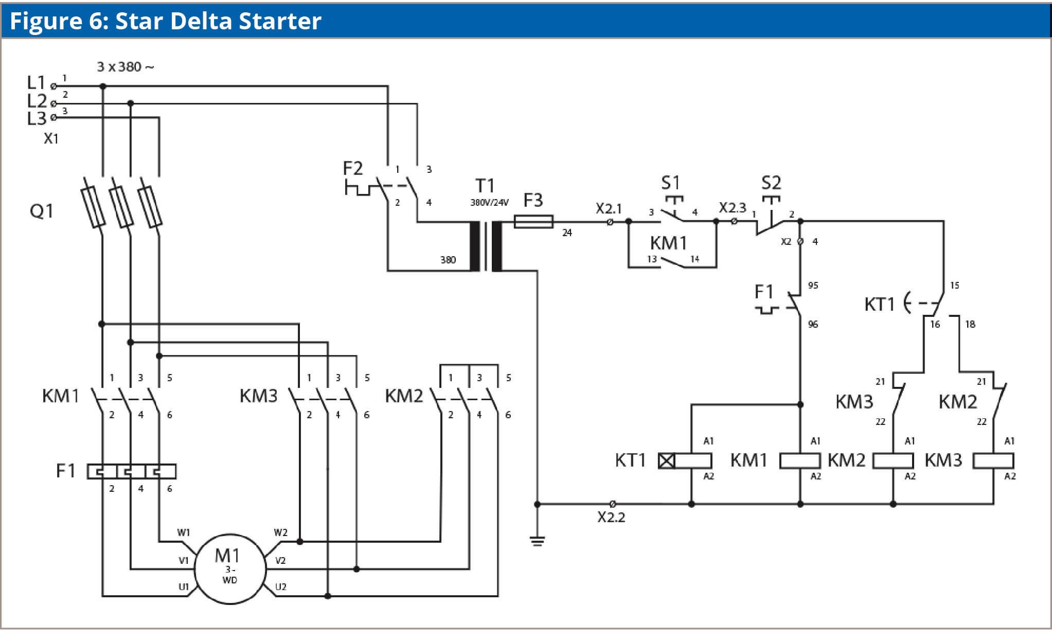
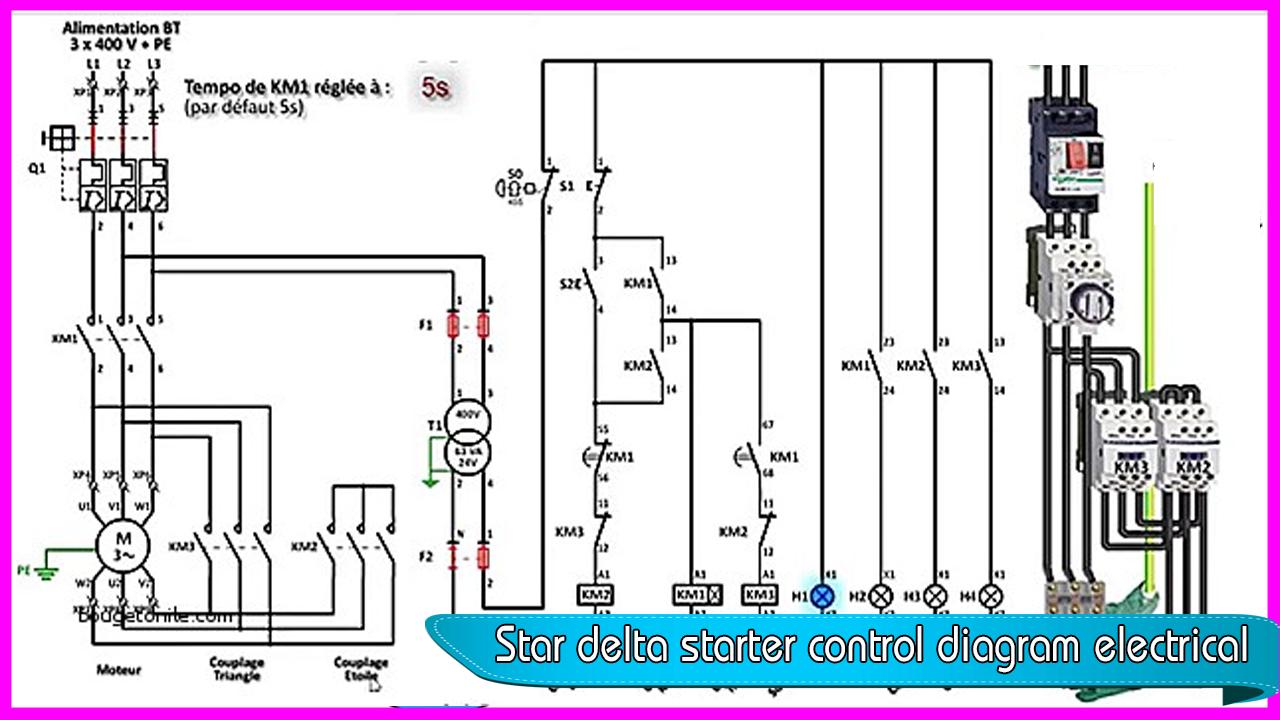
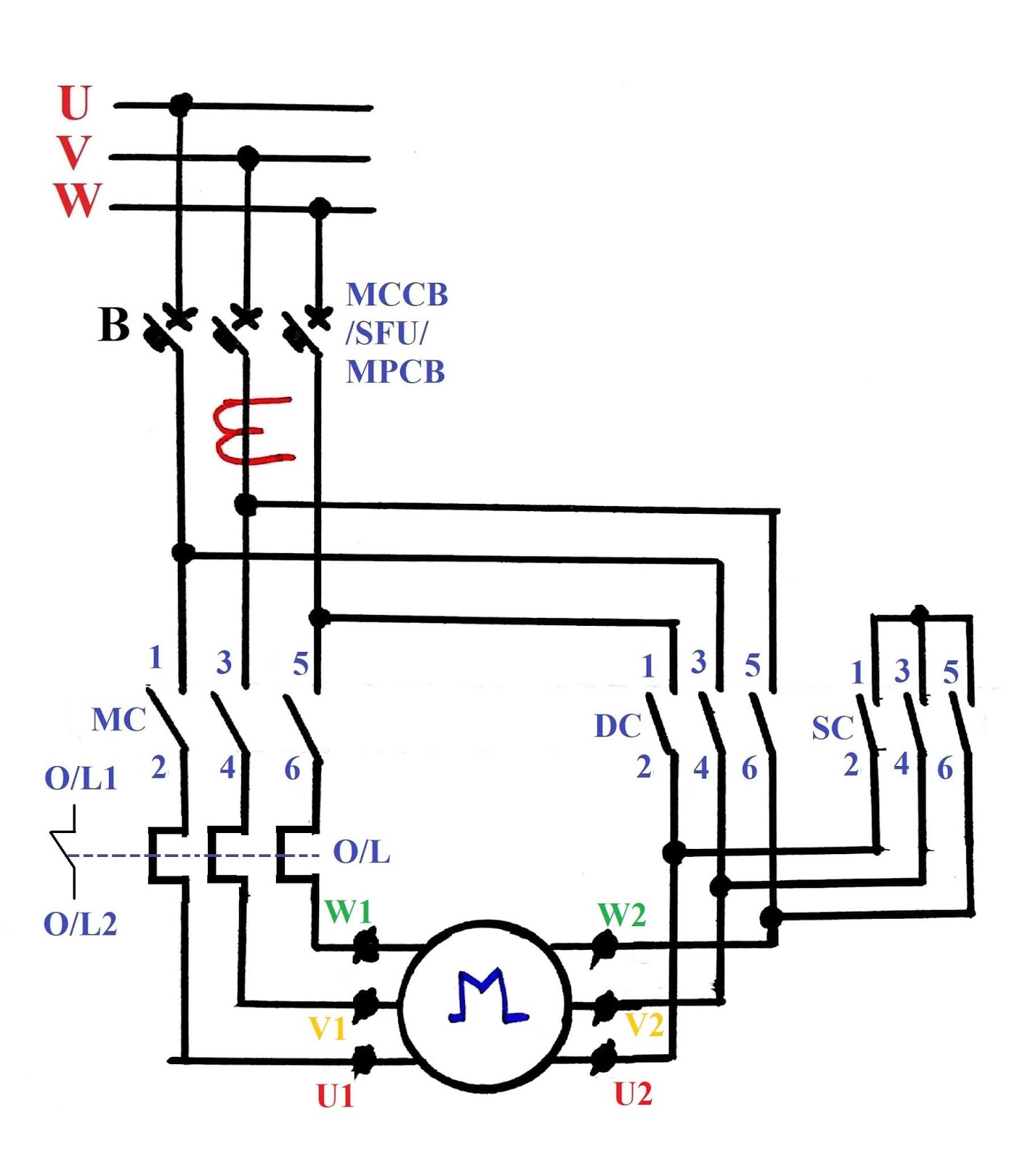
The control circuit uses to control the starter circuit such as on off and tripping operations. In the diagram of power circuit of star delta starter u2 and v2 of 3 phase motor should be connect to 4 and 6 respectively instead of u2 and v2 are connected to 6 and 4 of delta contector km2.

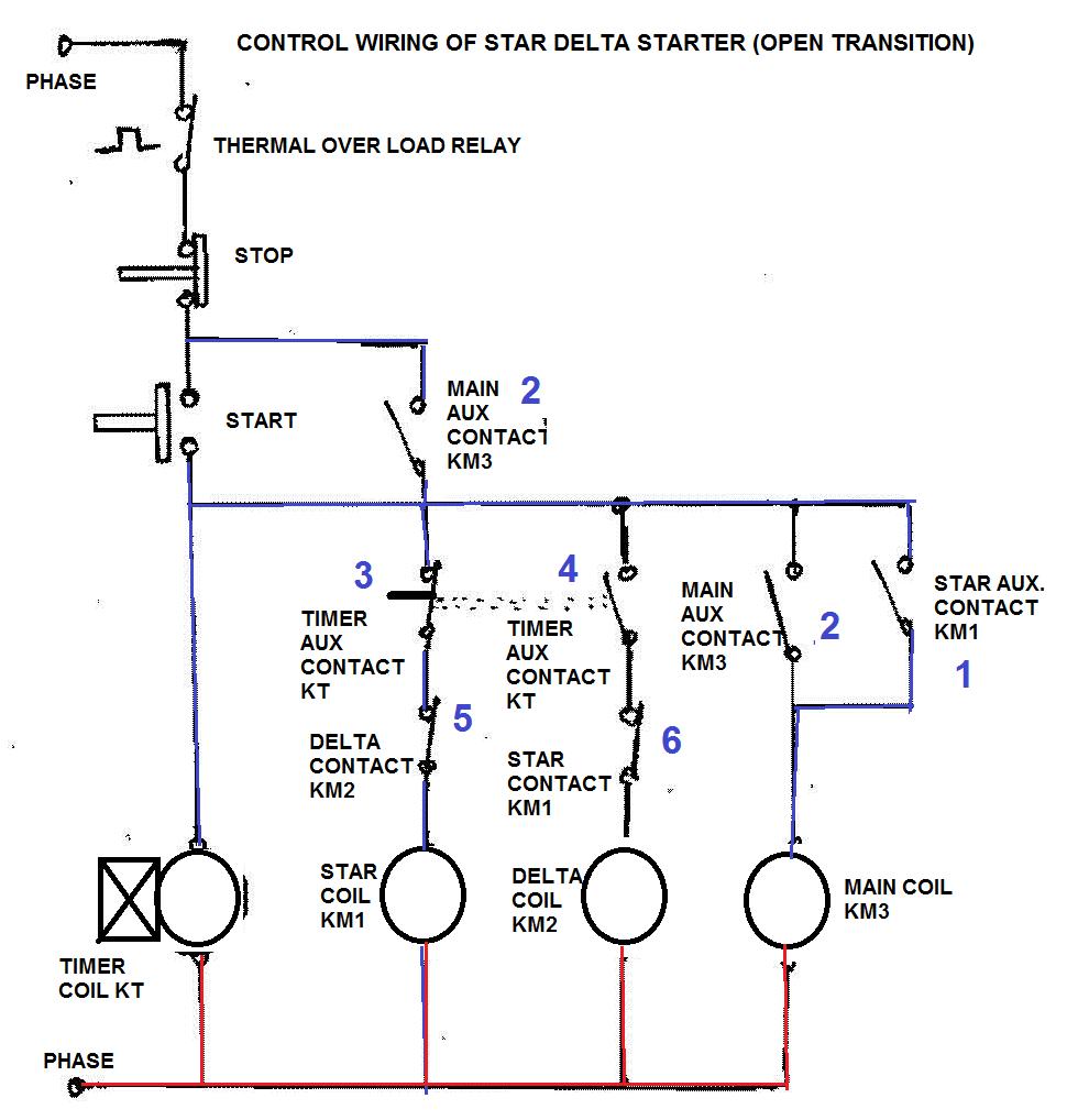
Control Circuit Of Star Delta Starter Electrical Info Pics
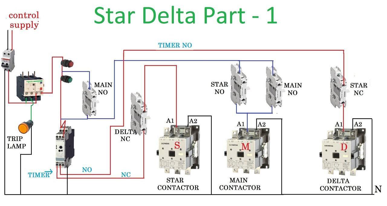
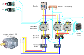
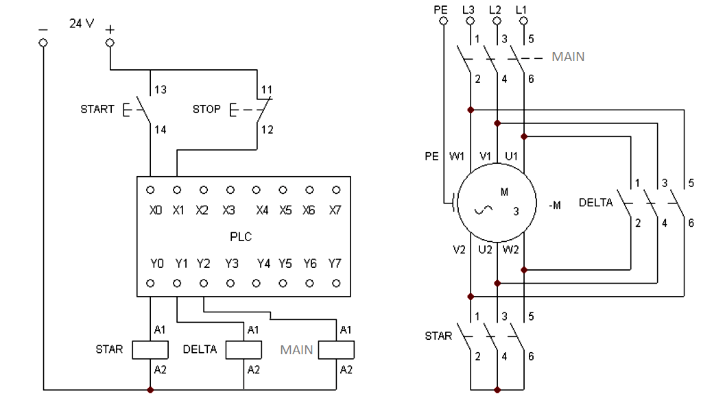
Wiring diagram of star delta starter. Star delta starter wiring diagram this post is about the main wiring connection of three phase motor with star delta starter and control wiring diagram of star delta starter. The power circuit uses to create contact between the motor and three phase power supply. This is a big advantage of a star delta starter as it typically has around 13 of the inrush current compared to a dol starter. For three phase motor we use the direct online starter but mostly for small three phase motor. Star delta connection circuit diagram. Of control star delta or wye delta suitable for applications requiring a lower starting current than when using dol starter.
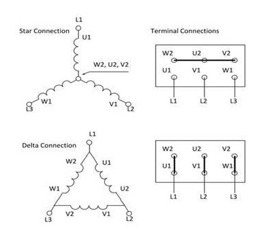
Star delta starters consist of a power circuit and control circuit. But high load 3 phase motor we use the star delta starter for motor. A star delta starter is a type of reduced voltage starterwe use it to reduce the starting current of the motor without using any external device or apparatus. There is minor correction is require to change printed in boxes sequence of 3 phase wires from w2 v2 u2 to w2 u2 v2 to get delta connection properly. Wiring diagram star delta connection in 3 phase induction motor. Refer to the below star delta circuit.
In this tutorial we will show the star delta y δ 3 phase induction ac motor starting method by automatic star delta starter with timer with schematic power control and wiring diagram as well as how star delta starter works and their applications with advantages and disadvantages.
Gallery of Wiring Diagram Of Star Delta Starter