However i am at a loss at how to wire it. In this video jamie shows you how to read a wiring diagram and the basics of hooking up an electric air compressor motor.

Baldor Electric Motor 5 Capacitor Wiring 3 Capacitor 5 Hp
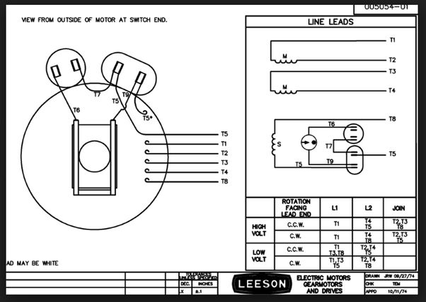
240v electric motor wiring diagram. Motors that are designed for 120240 volts. These diagrams are current at the time of publication check the wiring diagram supplied with the motor. Most electric motors have a wiring junction box typically on the rear of the motor on one side. It is a start capacitor and start run. Inst maint wiring5qxd 20112015 1137 am page 6. It reveals the components of the circuit as simplified shapes as well as the power and also signal connections in between the tools.
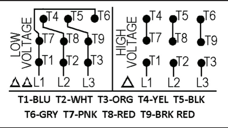
Single phase one fault cable arrangement single phase deutsch single phase induction motor single phase ac circuit analysis single phase flow single phase din typ wechselstromz hler single phase motor. It shows the components of the circuit as simplified shapes and also the power and signal connections in between the gadgets. These diagrams apply to intelligent control motorsthat are fitted to the following products pgs ocdeec. Single phase motor wiring diagram with capacitor baldor single phase motor wiring diagram with capacitor single phase fan motor wiring diagram with capacitor single phase motor connection diagram with capacitor every electrical arrangement is made up of various unique pieces. These tips can be used on most electric motor brands such as weg baldor. Variety of 240v motor wiring diagram single phase.
Open the wiring box cover by removing the screws and verify there are four wires inside the box for wiring the motor. A wiring diagram is a streamlined conventional pictorial depiction of an electric circuit. Read diagram of leg veins. Each component ought to be placed and linked to different parts in particular manner. I have been trying to google it for 3 days but am getting conflicting answers. This is where the cord or conduit attaches.
A wiring diagram is a simplified conventional photographic representation of an electrical circuit. Ic1 2 ocdeecvglgl. Gamma ec d 5051 diags. Changes in the wiring of an electric motor should only be made after the electric motor circuit has been identified and turned off and tagged. Refer to the motor manufacturers data on the motor for wiring diagrams on standard frame ex e ex d etc. Collection of electric motor wiring diagram 110 to 220.
Wiring diagram for electric motor with capacitor best single phase motor capacitor wiring diagram gooddy org. The wiring diagram will show that two of the motor wires are connected together for 240 volt wiring. I have recently fitted a new pump pressure switch and a 22kw3hp single phase 240v 2 pole electric to my compressor. Look at the underside of the cover for the wiring diagram which specifies which wires are used to wire the motor for 240 volts. Diagram ic2 m 1 240v ac 0 10v outp ut diagram ic3 m 1 0 10v 4 20ma 240v ac outp uts these diagrams are current at the time of publication check the wiring diagram supplied with the motor.
Gallery of 240v Electric Motor Wiring Diagram